Archive for July, 2013

Jul 19 2013

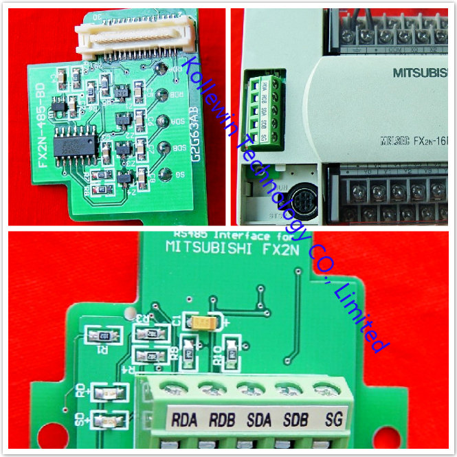
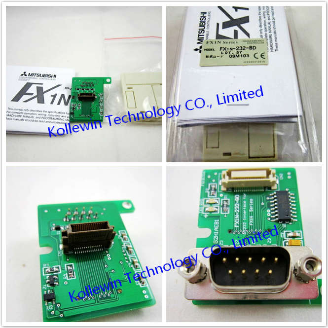
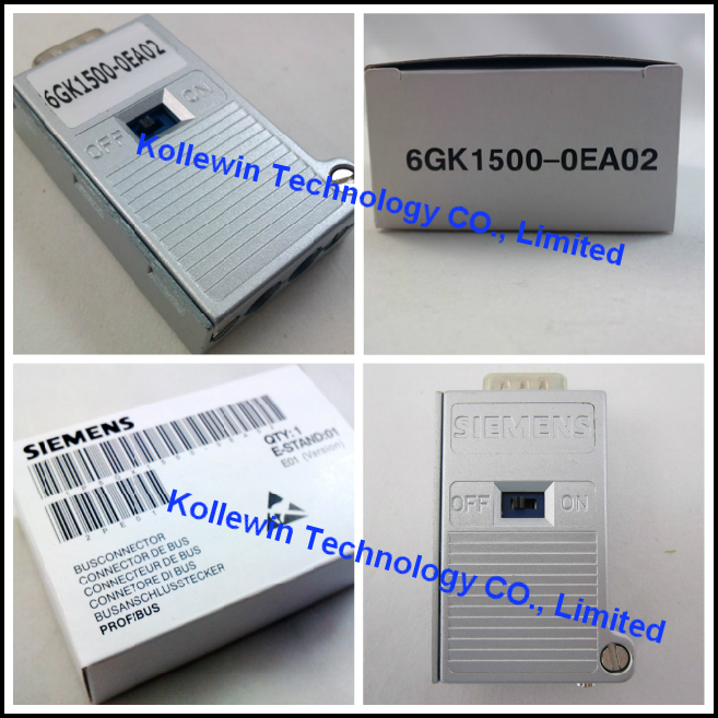
Mitsubishi FX1N-485-BD RS485 interface Board

Introduction to Mitsubishi FX1N-485-BD

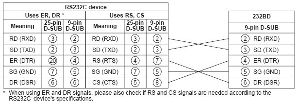
The RS-485 communication board FX1N-485-BD (hereafter referred to as "485BD") is connected to the FX1S/FX1N Series PLC basic unit, and available for the applications described below.
Only one function expansion board can be connected to one PLC basic unit. Accordingly, the 485BD cannot be used together with the FX1N-422-BD or the FX1N-232-BD.


1.1 Features of Mitsubishi FX1N-485-BD
1) Data transfer function using the non-procedure method.
The 485BD transfers the data using the RS instruction between a bar code reader, personal computer or printer.
As the 485BD is not equipped with buffer memory, it sends and receives the data using data registers specified by the RS instruction.
For the RS instruction and the communication setting, refer to the FX Series Communication User’s Manual.
2) Data transfer function using a dedicated protocol.
The 485BD transfers the data when a personal computer directly specifies devices of the PLC.
For the dedicated protocol and the communication setting, refer to the FX Series Communication User’s Manual.
3) Parallel link function.
The 485BD transfers automatically 50 auxiliary relays and 10 data registers when two FX1S Series PLC’s (two FX1N Series PLC’s) are connected on a one-to-one basis.
For the setting procedure and program examples, refer to the FX Series Communication User’s Manual.
4) Easy PC link function.
The 485BD transfers automatically up to 64 auxiliary relays and 8 data registers when up to eight FX1S/FX1N/FX0N/FX2N/FX2NC Series PLC units are connected. For the setting procedure and program examples, refer to the FX Series Communication User’s Manual. For the FX2N Series PLC, the version should be 2.00 or greater (manufacturer’s serial No. 780000 or later).


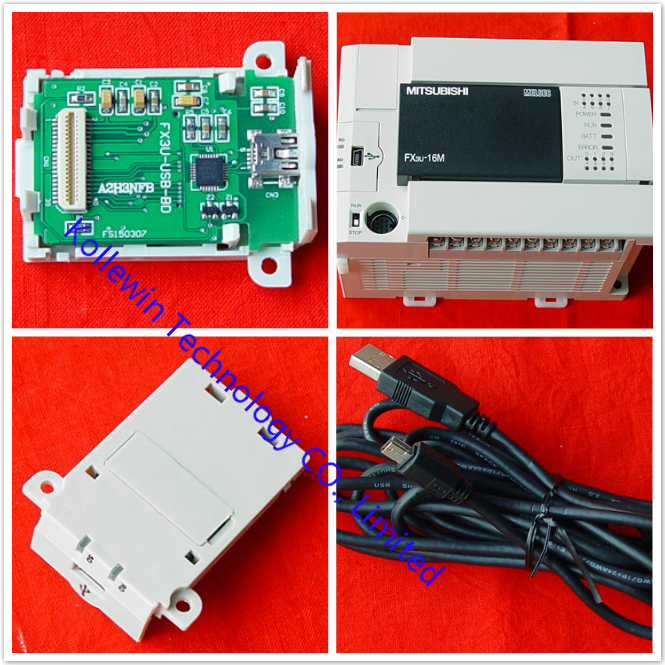
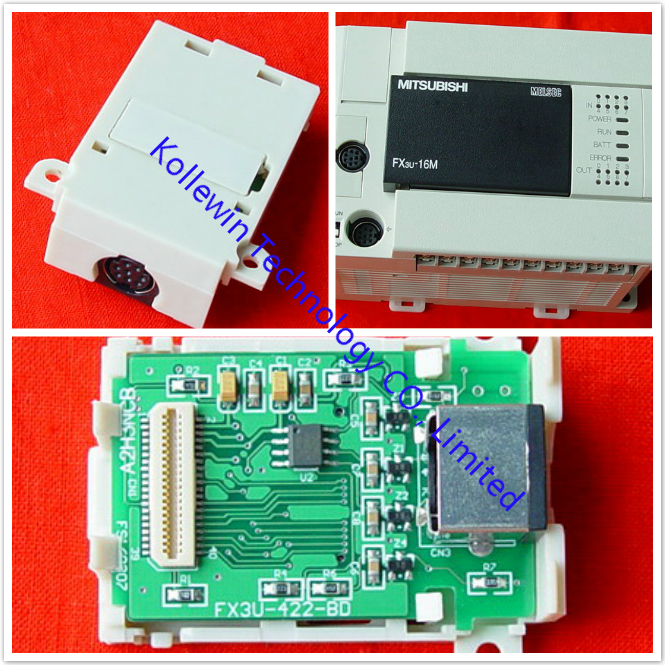
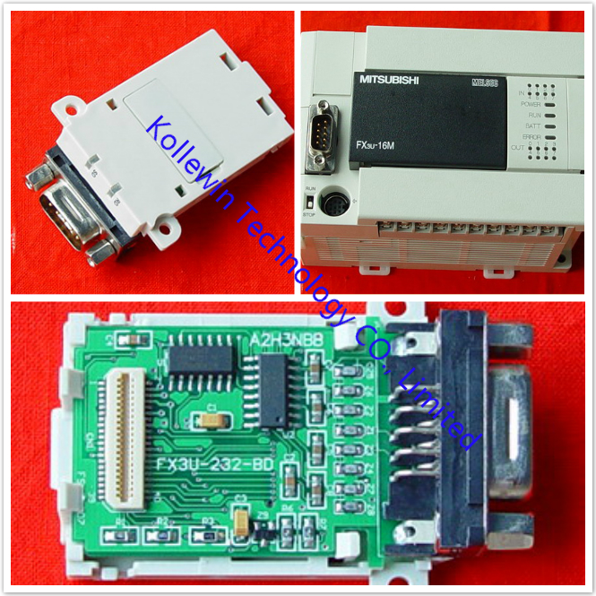
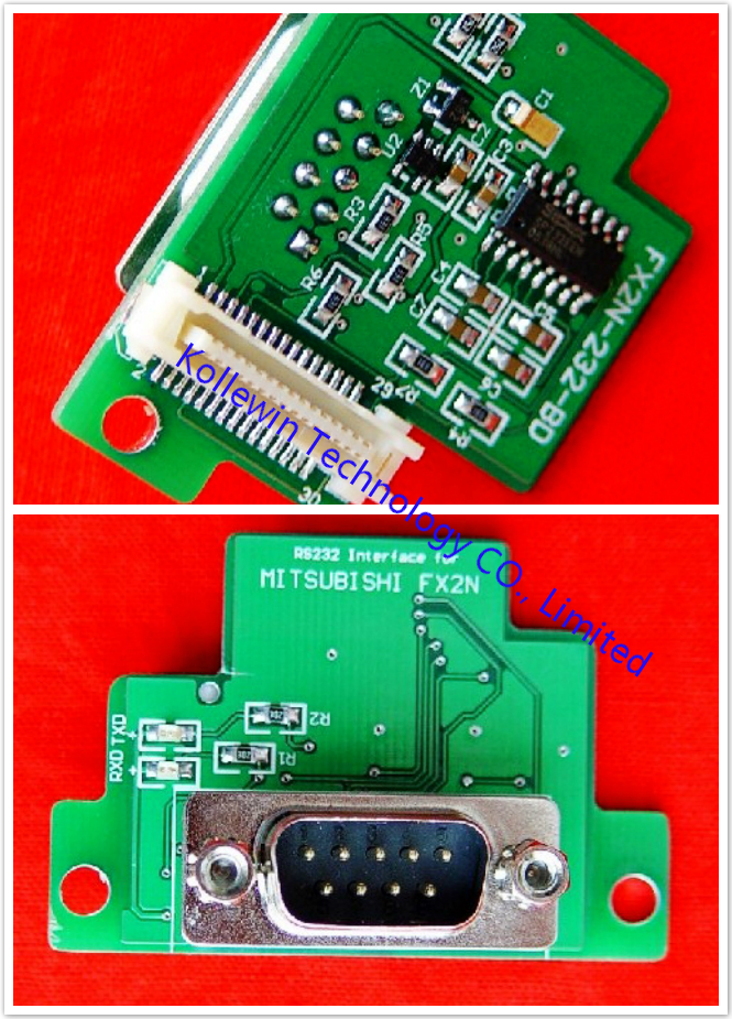
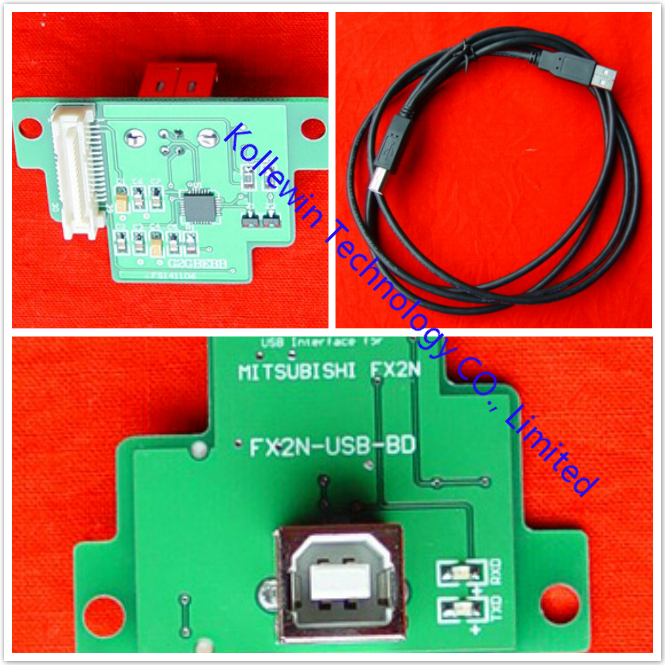
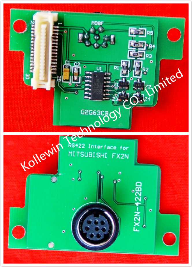
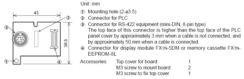
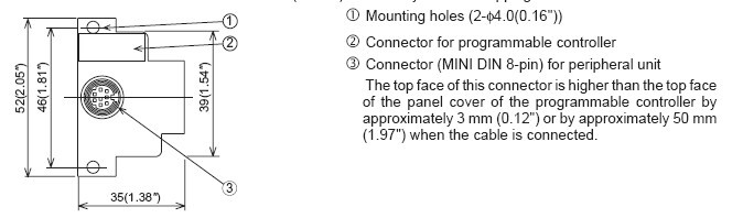
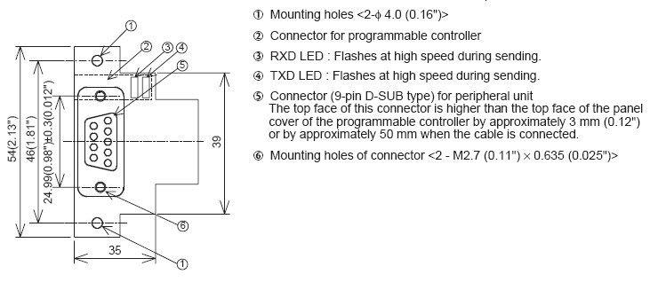
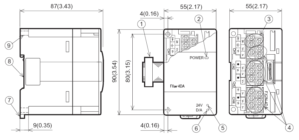
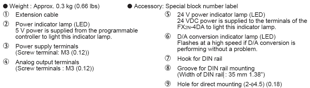
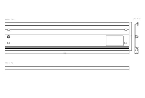
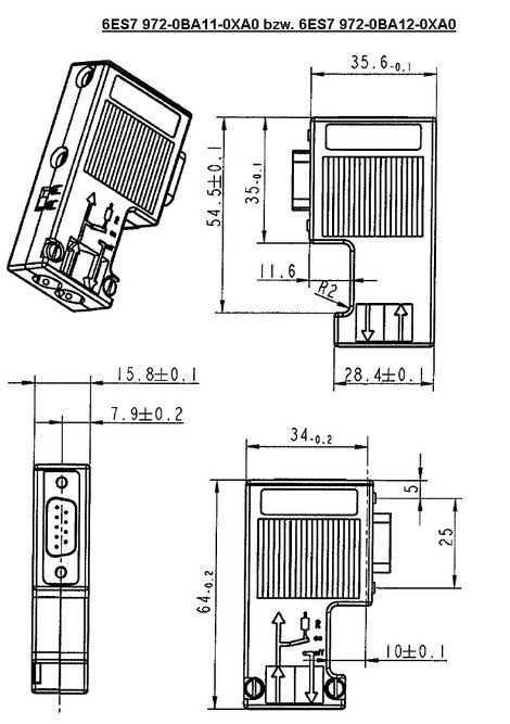
1.2 Outside dimensions and name of each part for Mitsubishi FX1N-485-BD
 

1


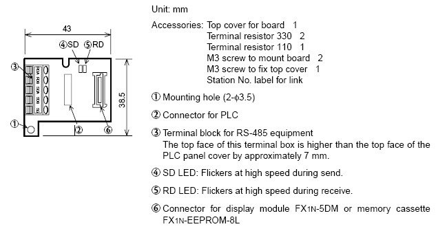
1.3 System configuration of Mitsubishi FX1N-485-BD

For the system configuration, refer to the FX Series Communication User’s Manual offered separately.


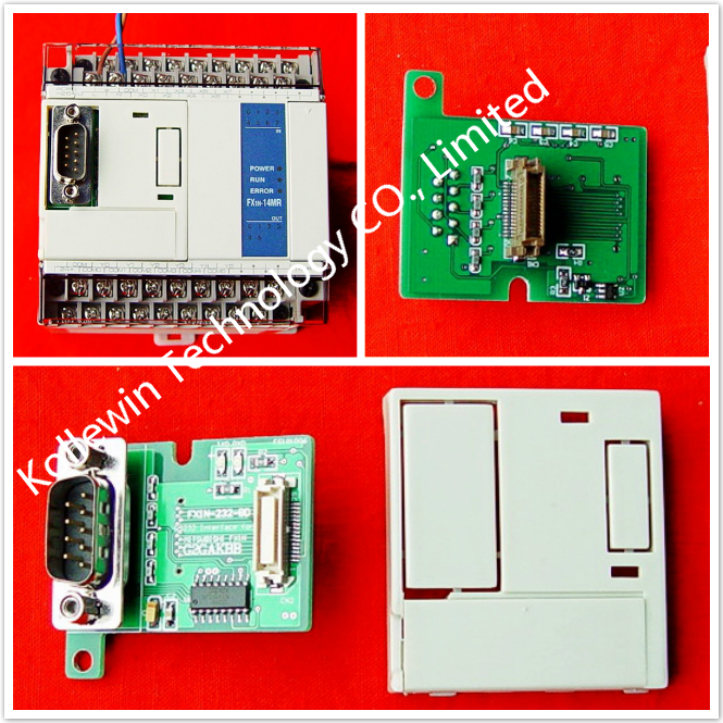
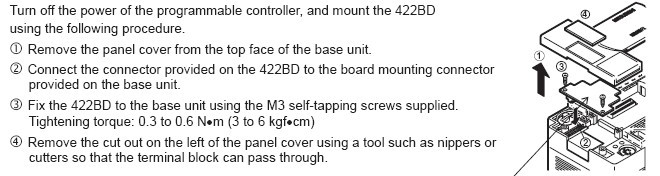
Installation of Mitsubishi FX1N-485-BD
 

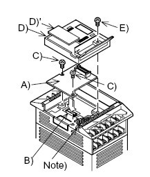
2.1 Installation procedure of Mitsubishi FX1N-485-BD
 

2
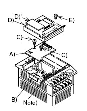
Make sure to turn off the power before installing the 485BD.
A) Communication board 485BD (function expansion board)
B) Connector for optional equipment
C)M3 screw to fix board (2 pieces) (offered as accessories of board)
D) Top cover for board (offered as an accessory of board)
E) M3 screw to fix top cover (offered as an accessory of board)
Note: This screw cannot be removed.
• Plug the communication board A) in to the connector B).
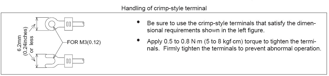
• Fix the board to the basic unit with two M3 screws C). (Tightening torque: 0.3 to 0.6 Nxm)
• Remove the top cover of the basic unit, and attach the top cover for board D) instead.
During attachment, remove D)’ with a nipper, etc. so that the connector of the board is exposed.
• Fix the top cover with the M3 screw E). (Tightening torque: 0.3 to 0.6 Nxm)
• When the FX1N-5DM is used also, refer to the handy manual offered with the FX1S/FX1N Series PLC main unit.
• Only one function expansion board is available for one FX1S/FX1N Series PLC basic unit. Never stack up two or more function expansion boards. (Even if they are stacked up, they do not function at all.)


Specifications of Mitsubishi FX1N-485-BD

3.1 Environmental specifications of Mitsubishi FX1N-485-BD
The environmental specifications are equivalent to those of the PLC main unit. (Refer to the manual of the PLC main unit.)


3.2 Power supply specifications of Mitsubishi FX1N-485-BD
5V DC, 60 mA is supplied as the power from the PLC.


3.3 Performance specifications of Mitsubishi FX1N-485-BD

Transmission standard Description
Maximum transmission
distance
In conformance to RS-485 and RS-422
Communication type Non-procedure, dedicated protocol, parallel link, easy PC link: Half
duplex, bi-directional
Communication method Non-procedure, dedicated protocol 1 procedure, dedicated protocol 4
procedure, parallel link, easy PC link
Transmission speed
(baud rate)
Non-procedure, dedicated protocol: 300 to 19,200 b ps
Parallel link: 19,200(b ps)
Easy PC link: 38,400(b ps)
Insulation Not insulated


Guidelines for the safety of the user and protection to the RS-485 Communication Board FX1N-485-BD
• This manual has been written to be used by trained and competent personnel. This is defined by the European directives for machinery, low voltage and EMC.
• If in doubt at any stage during the installation of the RS-485 Communication Board FX1N-485-BD always consult a professional electrical engineer who is qualified and trained to the local and national standards. If in doubt about the operation or use of the RS-485 Communication Board FX1N-485-BD please consult the nearest Mitsubishi Electric distributor.
• Under no circumstances will Mitsubishi Electric be liable or responsible for any consequential damage that may arise as a result of the installation or use of this equipment.
• All examples and diagrams shown in this manual are intended only as an aid to understanding the text, not to guarantee operation. Mitsubishi Electric will accept no responsibility for actual use of the product based on these illustrative examples.
• Owing to the very great variety in possible application of this equipment, you must satisfy yourself as to its suitability for your specific application. 


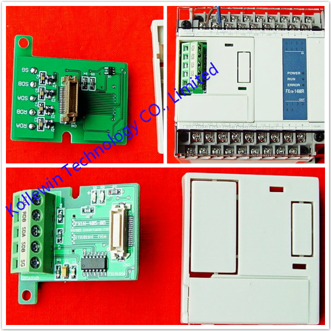
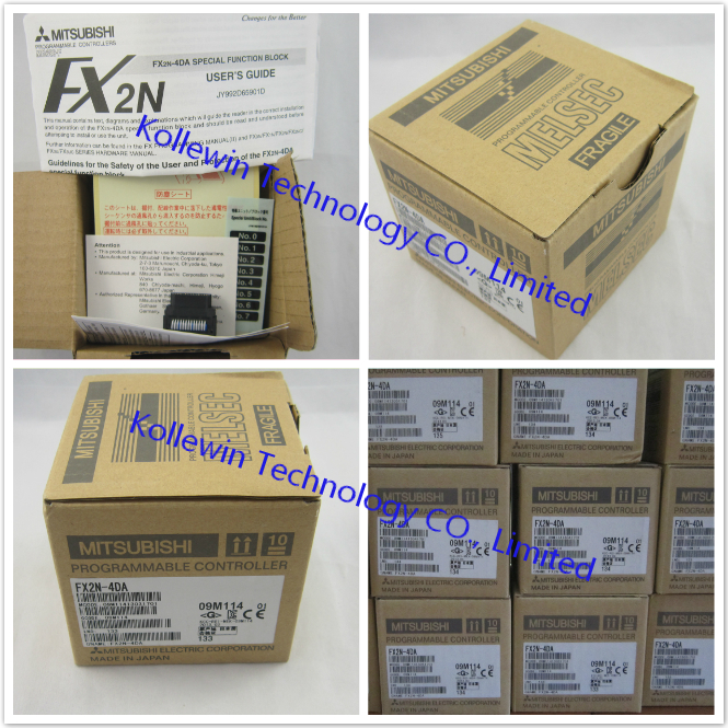
Our company (Kollewin Technology CO., Limited) have a new product, named FX1N-485-BD.

It is 100% compatible with Mitsubishi original FX1N-485-BD.


Part#: FX1N-485-BD

The unit price is USD21.69/pc  buy buttom


USER'S MUNUAL PDF of Mitsubishi communication board FX1N-485-BD:

RS-485 COMMUNICATION BOARD FX1N-485-BD


FX1N-485-BD


Specification of Mitsubishi communication board FX1N-485-BD:

Product Name Communication Board
Fit for Mitsubishi FX1N PLC
Model NO. FX1N-485-BD
External Connector Type In Conformance to RS-485
Voltage DC 5V
Current 40mA
Max.Transmission Distance 15M
Communication Method Half-duplex
Insulation No Insulated
Material Plastic, Metal
Net Weight 18g
Package Content

1 x Communication Board

1 x Top Cover

Several Install Parts


Description of RS485 Communication Board for Mitsubishi FX1N-485-BD:

  • The FX1N combines the benefits of an inexpensive compact controller with the flexible expansion capabilities of a modular control system.
  • This is a Replacement of Mitsubishi FX1N-485-BD Programmable Controller.
  • This is OEM product, not Mitsubishi original part.


More communication boards, please click below links:

FX2N-485-BD+

FX2N-485-BD

FX2N-422-BD

FX2N-232-BD

FX1N-485-BD

FX1N-422-BD

FX3U-485-BD

FX3U-422-BD

FX3U-232-BD

FX3U-USB-BD

FX2N-4DA


More pictures of communication board 

FX1N-USB-BD-1 FX3U-USB-BD FX3U-CNV-BD FX3U-485-BD FX3U-422-BD FX3U-232-BD FX2N-485-BD+ FX2N-485-BD FX2N-232-BD FX1N-422-BD FX2N-USB-BD-1 FX2N-422-BD FX2N-485-BD FX1N-232-BD -1 FX1N-232-BD


Please feel free to contact me for any question!

Contact person: Miss Nancy

Skype: kollewin
E-mail: nancy@kollewin.com
Tel: +86-0755-26898905-8006
Website: www.kollewin.com
Jul 18 2013

Mitsubishi FX1N-422-BD RS422 interface Board

Introduction to Mitsubishi FX1N-422-BD


The RS-422 communication board FX1N-422-BD (hereafter reaferred to as "422BD") is connected to the FX1S/FX1N
Series PLC basic unit, and used as a connection port for a programming tool (such as the GOT Series, the ET Series,programming tool FX-10P/20P or personal computer).
For example, by using the 422BD, two GOT Series units can be connected to the FX1S/FX1N Series PLC, or the GOT Series unit can be connected to a programming tool (such as FX-10P, FX-20P or personal computer). However, a programming tool can be connected to only either one between the connector built in the PLC and the connector of the 422BD.
Only one function expansion board can be connected to one PLC basic unit. Accordingly, the 422BD cannot be used together with the FX1N-485-BD or the FX1N-232-BD.


Outside Dimensions and Name of Each Part of Mitsubishi FX1N-422-BD

32


Connectable Models and Cables of Mitsubishi FX1N-422-BD

Peripheral equipment   Cable   Current consumption of 5V DC  
FX-20P   FX-20P-CAB0 or
(FX-20P-CAB + FX-20P-CADP)
180mA  
FX-10P   120mA  
Personal computer (for programming)   {F2-232CAB (for D-sub, 25-pin type),
F2-232CAB-1 (for D-sub, 9-pin type) or
F2-232CAB-2 (for half-pitch, 14-pin type)}
+ FX-232AW(C) + FX-422CAB0
220mA  
FX-10DM   FX-20P-CAB0 or FX-20P-CAB + FX-20P-CADP   180mA  
F930GOT, F940GOT,
ET-940, F940/943GOT
(handy type)
FX-50DU-CAB0   Not required  
FX-40DU-CAB(-10M) (or equivalent cable) + FX-422AW0 180mA


Installation of Mitsubishi FX1N-422-BD

31
Make sure to turn off the power before installing the 422BD.
A) Communication board 422BD (function expansion board)
B) Connector for optional equipment
C) M3 screw to fix board (2 pieces) (offered as accessories of board)
D) Top cover for board (offered as an accessory of board)
E) M3 screw to fix top cover (offered as an accessory of board)
Note: This screw cannot be removed.
• Plug the communication board A) in to the connector B).
• Fix the board to the basic unit with two M3 screws C). (Tightening torque: 0.3 to 0.6 Nžm)
• Remove the top cover of the basic unit, and attach the top cover for board D) instead.
During attachment, remove D)’ with a nipper, etc. so that the connector of the board is exposed.
• Fix the top cover with the M3 screw E). (Tightening torque: 0.3 to 0.6 Nžm)
• When the FX1N-5DM is used also, refer to the handy manual offered with the FX1S/FX1N Series PLC main unit.
• Only one function expansion board is available for one FX1S/FX1N Series PLC basic unit. Never stack up two or
more function expansion boards. (Even if they are stacked up, they do not function at all.)


Specifications of Mitsubishi FX1N-422-BD
5.1 Environmental specifications
of RS422 interface PLC Communication Board

The environmental specifications are equivalent to those of the PLC main unit. (Refer to the manual of the PLC main unit.)


5.2 Power supply specifications of RS422 interface PLC Communication Board
5V DC, 60 mA is supplied as the power from the PLC.
For the details, refer to the handy manual of the PLC main unit.


5.3 Performance specifications  of RS422 interface PLC Communication Board

Transmission standard In conformance to RS-232C
Maximum transmission distance 50 m maximum
External equipment connection method Mini-DIN, 8-pin socket
D-sub 9-pin Layout 1: CD 2: RD(RXD) 3: SD(TXD) 4: ER(DTR) 5: SG(GND)
6: DR(DSR) 7, 8, 9: NC (not used)
Communication method Half duplex, bi-directional
Protocol Protocol for programming tool
Isolation No insulated


Our company (Kollewin Technology CO., Limited) have a new product, named FX1N-422-BD.

It is 100% compatible with Mitsubishi original FX1N-422-BD.


Part#: FX1N-422-BD

The unit price is USD21.69/pc   buy buttom


USER'S MUNUAL PDF of communication board FX1N-422-BD: 

FX1N-422-BD-USER'S MANUAL

FX1N-422-BD


Specification of communication board FX1N-422-BD:

Product Name Communication Board
Fit for for Mitsubishi FX1N PLC
Model No. FX1N-422-BD
Transmission Stanndard In Comformance to RS-422
External Connector Type Mini-DIN 8 Pin
Voltage DC 5V
Current 60mA
Max.Transmission Distance 50M
Material Metal, Plastic


Description of communication board FX1N-422-BD:

  • The RS-422 communication board FX1N-422-BD (hereafter referred to as "422BD") is connected to the FX1S/FX1N Series PLC basic unit, and used as a connection port for a programming tool (such as the GOT Series,the ET Series,programming tool FX-10P/20P or personal computer).
  • This is OEM product, not Mitsubishi original part.


More communication boards, please click below links:

FX2N-485-BD+

FX2N-485-BD

FX2N-422-BD

FX2N-232-BD

FX1N-485-BD

FX1N-422-BD

FX3U-485-BD

FX3U-422-BD

FX3U-232-BD

FX3U-USB-BD

FX2N-4DA


More pictures of communication board 

FX1N-USB-BD-1 FX3U-USB-BD FX3U-CNV-BD FX3U-485-BD FX3U-422-BD FX3U-232-BD FX2N-485-BD+ FX2N-485-BD FX2N-232-BD FX1N-485-BD FX2N-USB-BD-1 FX2N-422-BD FX1N-232-BD FX1N-232-BD -1


Please feel free to contact me for any question!

Contact person: Miss Nancy

Skype: kollewin
E-mail: nancy@kollewin.com
Tel: +86-0755-26898905-8006
Website: www.kollewin.com
Jul 17 2013

Mitsubishi FX2N-422-BD RS422 interface Board

Introduction to Mitsubishi FX2N-422-BD

The FX2N-422-BD for RS422 communication board (422BD) can be connected to an FX2N Series programmable
controller, and used as a port for programming and monitoring tools.
When the 422BD is used, two DU Series units can be connected to the FX2N or a DU Series unit and a
programming tool. However, only one programming tool can be connected at once.
Only one 422BD can be connected to a base unit. Also, the 422BD cannot be used together with the
FX2N-485-BD or the FX2N-232-BD.


External Dimensions of Mitsubishi FX2N-422-BD

Dimensions : mm (inches) Accessory : M3 self-tapping screws ´ 2

10


Suitable Products and Connecting Cables for Mitsubishi FX2N-422-BD

 Product    Connecting cable    Required 5V DC  
 FX-20P-E   FX-20P-CAB0 or FX-20P-CAB + FX-20P-CADP    180mA  
 FX-10P-E    120mA  
 Personal computer   F2-232CAB-1 + FX-232AW(C) + (FX-422ACB0 or
FX-422CAB + FX-20P-CADP) *1
 220mA  
 FX-10DU-E   FX-20P-CAB0 or FX-20P-CAB + FX-20P-CADP    220mA  
 FX-20DU-E   FX-20DU-CAB0 or FX-20DU-CAB + FX-20P-CADP    180mA  
 FX-25DU-E,FX-30DU-E,
 FX-40DU-ES,FX-40DU-TK-ES,
 FX-50DU-TK(S)-E *2 
FX-50DU-CAB0 or FX-40DU-CAB + FX-20P-CADP  

 30mA  

*1: When using other products or cables please check the product manual for required 5V DC supply.
*2: FX-2PIF can not be connected to the FX2N-422-BD.


Mounting procedure for using Mitsubishi FX2N-422-BD

11


Specification of Mitsubishi FX2N-422-BD
5.1 General specification of RS422 interface PLC communication Board
General specifications are the same as those for the FX2N series programmable controller.


5.2 Power supply specification of RS422 interface PLC communication Board
The 422BD requires 60mA 5V DC supplied from the programmable controller.
The 5V DC power capacity of the programmable controller is 290 mA maximum. This is used by peripheral units and special function blocks as well as the 422BD. Make sure that the power capacity does not exceed this value. For the details, refer to the hardware manual.
For additional current consumption increases, refer to section 3.


5.3 Performance specification of RS422 interface PLC communication Board

Interface Conforming to RS422
Maximum transfer distance Total extension within 50m.
Connector MINI DIN 8 pin
Communication method Half-duplex communication system
Protocol Programming protocol
Isolation No isolation


Cautions for using Mitsubishi FX2N-422-BD
1) When using any 422BD, do not use any other communication format or parameters. If the communication format or parameters is set, programming is not possible.
2) Only one programming tool (such as FX-10P, FX-20P, etc.) should be connected to either the programming port or the port provided on the 422BD. If a programming tool is connected to both connectors, the following may occur.
a) The program inside the programmable controller may not be consistent with the program inside the programming tool. If the program is modified or the set value for timers or counters is modified, a part of the program may be damaged and the programmable controller may malfunction.
b) When the sampling trace function of the programmable controller is used from both ports, the correct sampling trace result cannot be obtained.


Diagnostics of Mitsubishi FX2N-422-BD
1) Make sure that the cable connected is correct.
2) Make sure that the programmable controller is connected, and that the POWER LED is on.
3) Make sure that the communication format is in the initial state (D8120 = K0). Check using a peripheral unit how the communication parameters are set. If the no protocol (RS instruction) or the dedicated protocol is selected, set the parameters correctly using the peripheral unit.
4) Make sure that the RS, VRRD or VRSC instruction or N:N network setting program is not used in the program. If such an instruction is used in the program, delete it, turn off the power of the programmable controller, then turn it on again.
5) If the special auxiliary relay M8070 or M8071 is turned on, turn off the relay using the peripheral unit, turn off the power of the programmable controller, then turn on the power again.


Our company (Kollewin Technology CO., Limited) have a new product, named FX2N-422-BD.

It is 100% compatible with Mitsubishi original FX2N-422-BD.

Part#: FX2N-422-BD

The unit price is USD17.65/pc  buy buttom


USER'S MUNUAL PDF OF RS422 interface PLC Communication Board FX2N-422-BD:

FX2N-422-BD-USER'S MANUAL

FX2N-422-BD


Specification of communication board FX2N-422-BD:

Interface Conforming to RS422
Maximum transfer distance Total extension within 50m.
Connector MINI DIN 8 pin
Communication method Half-duplex communication system
Protocol Programming protocol
Isolation No isolation
   
Product Name Communication Board
Fit for Mitsubishi FX2N PLC
Model NO. FX2N -422-BD
Interface Conforming to RS422
Connector Type Mini Din 8 Pin
Voltage DC 5V
Current 60mA
Max.Transmission Distance 50M
Communication Method Half-duplex(Communication System)
Insulation No Insulated
Material Plastic, Metal


Description of communication board FX2N-422-BD:

  • The FX2N-422-BD for RS-422 Communication Board(422BD)can be connected to an FX2N series programmable controller, and used as a port programming and monitoring tools.
  • This is a Replacement of Mitsubishi FX2N-422-BD Programmable Controller.
  • This is OEM product, not Mitsubishi original part.


More communication boards, please click below links:

FX2N-485-BD+

FX2N-485-BD

FX2N-422-BD

FX2N-232-BD

FX1N-485-BD

FX1N-422-BD

FX3U-485-BD

FX3U-422-BD

FX3U-232-BD

FX3U-USB-BD

FX2N-4DA


More pictures of Communication Board 

FX2N-USB-BD-1 FX1N-422-BD FX1N-485-BD FX2N-232-BD FX2N-485-BD FX2N-485-BD+ FX1N-USB-BD-1 FX3U-USB-BD FX3U-CNV-BD FX3U-485-BD FX3U-422-BD FX3U-232-BD


Please feel free to contact me for any question!

Contact person: Miss Nancy

Skype: kollewin
E-mail: nancy@kollewin.com
Tel: +86-0755-26898905-8006
Website: www.kollewin.com
Jul 16 2013

Mitsubishi FX2N-232-BD RS232 interface Board

Introduction to Mitsubishi FX2N-232-BD


The communication board FX2N-232-BD for RS232C (hereinafter referred to as “232BD”) can be connected to the main unit of the FX2N Series programmable controller, and used as the port for the following applications.
(1) To perform data transfer between RS232C devices such as personal computers, bar code readers and printers.
(2) To perform data transfer using the dedicated protocol between RS232C devices. For details of the dedicated protocol, refer to the users manual of the FX-485PC-IF.
(3) To connect a programming tool.
And when the 232BD is used for the application (1) or (2) above, the communication format including the baud rate, the parity and the data length is specified by the parameters or the contents of the special data register D8120 of the FX2N programmable controller.
Only one 232BD can be connected to one base unit. Accordingly, the 232BD cannot be used together with the FX2N-485-BD or the FX2N-422-BD. When two or more RS232C units are required to be connected for the application, use the special block for RS232C communication.


1.1 EXTERNAL DIMENSIONS of Mitsubishi FX2N-232-BD
Dimensions : mm (inches) Accessory : M3 self-tapping screws ´ 2, mounting bracket ´ 2

23


TERMINAL LAYOUTS of Mitsubishi FX2N-232-BD

The connector is a 9-pin D-SUB type, and the pin configuration is as shown below.

24

Pin No. Signal Meaning Function
1 CD(DCD) CD(DCD) ON when carrier is detected for data reception
2 RD(RXD) Receive data Receive data (RS232C device to 232BD)
3 SD(TXD) Send data Send data (232BD to RS232C device)
4 ER(DTR) Send request Signal requesting preparation for data sending to RS232C
device
5 SG(GND) Signal ground Signal ground
6 DR(DSR) Send enable Shows RS232C device is ready to receive
7,8,9 NC No connection


SPECIFICATION of Mitsubishi FX2N-232-BD

3.1 General specification of RS232 interface PLC comunication Board
General specifications is same as those for the FX2N series programmable controller.


3.2 Power supply specification of RS232 interface PLC comunication Board
5 V DC, 60 mA is required from the programmable controller.


3.3 Specification of RS232 interface PLC comunication Board

Transmission standard Conforming to RS232C
Transmission distance Max. 15m
Connector 9-pin D-SUB type
Pin layout of connector 1:CD(DCD) 2:RD(RXD) 3:SD(TXD) 4:ER(DTR) 5:SG(GND) 6:DR(DSR)
7,8,9:NC(No connection)
LED indicators RXD, TXD
Communication method Half-duplex communication system
Protocol Programming protocol, dedicated protocol (format 1 or 4), non protocol
Isolation No isolation


3.4 Related flag and data registers of RS232 interface PLC comunication Board

Diagnostic   devices Operation
M8121  Data transmission delayed (RS instruction)
M8122  Data transmission flag (RS instruction)
M8123  Finished receiving data (RS instruction)
M8124  Carrier detection flag (RS instruction)
M8126  Global flag (dedicated protocol)
M8127  On demand handshake flag (dedicated protocol)
M8128 On demand error flag (dedicated protocol)
M8129  On demand Byte/Word flag (dedicated protocol)
M8161  Selection of 8 bit operations for applied instructions
ASC, RS, ASCI, HEX, CCD (RS instruction)
   
Diagnostic devices Operation
D8120  Communications format (RS instruction, dedicated protocol)
D8121  Local station number (dedicated protocol)
D8122  Amount of data to be transmitted (RS instruction)
D8123  Amount of remaining data already received (RS instruction)
D8124  Data header <default STX (02H)> (RS instruction)
D8125  Data terminator <default ETX (03H)> (RS instruction)
D8127  On demand head device register (dedicated protocol)
D8128  On demand data length register (dedicated protocol)
D8129  Data network ‘time-out’ timer value (dedicated protocol)


3.5 Communication format D8120  of Mitsubishi FX2N-232-BD
To send and receive the data between the RS232C unit using the 232BD, the communication format including the
transmission speed (baud rate) and the parity must be consistent between the 232BD and the RS232C unit.
The communication format can be set using parameters or the contents of special data register D8120 of the FX2N programmable controller. Make sure to set appropriately the communication format in accordance with the RS232C unit used. For the setting method using the parameters of the FX2N programmable controller, refer to the manual of the peripheral unit used.
Make sure to turn off the power of the programmable controller and turn it on again after modifying the setting.

25

*1 Set to “0" when using the dedicated protocol.
*2 Effective only when no protocol (RS instruction) is selected, and has an initial value of STX (02H: Can be modified by
the user).
*3 Effective only when no protocol (RS instruction) is selected, and has an initial value of ETX (03H: Can be modified by
the user).
*4 Set to (b11, b12) = (1, 0) when using the dedicated protocol.
*5 Set to “0" when using no protocol. 


3.5.1 Example program of setting of Mitsubishi FX2N-232-BD
26

The control line is set by b12.
b12 = 0 : No hardware hand shaking. Send and receive are controlled by software protocol.
b12 = 1 : Hardware hand shaking. Signal lines ER(DTR)and DR(DSR)are used to control send and receive of data.

27


WIRING of Mitsubishi FX2N-232-BD

To connect the 232BD to RS232C device use an RS232C cable. Make sure that the shield of cables is connected to
ground (100 W or less).
The connector of the 232BD is 9-pin D-SUB (see Section 1.2 and Chapter 2). The connections of RS232C devices
varies with each device being used. Check the specification of the device, and connect.
4.1 Connection examples
4.1.1 Terminal specification device
of RS232 interface PLC comunication Board

28


4.1.2 Modem specification device of RS232 interface PLC comunication Board

29


4.1.3 When programming or monitoring of Mitsubishi FX2N-232-BD
Use F2-232CAB-1 and 25-pin D-SUB to 9-pin D-SUB adapter or make a suitable cable.


CAUTION for using Mitsubishi FX2N-232-BD

1) When programming tool is connected the 232BD, do not use any other communication format or parameters. If communication format or parameters is set, programming is not possible.
2) Only one programming tool (such as FX-10P, FX-20P, etc.) should be connected to either the programming port or the port provided on the 232BD. If a programming tool is connected to both connectors, the following may occur.
a) The program inside the programmable controller may not be consistent with the program inside the programming tool. If the program is modified or the set value for the timer or the counter is modified, a part of the program may be damaged and the programmable controller may malfunction.
b) When the sampling trace function of the programmable controller is used from both ports, the correct sampling trace result cannot be obtained.


Our company (Kollewin Technology CO., Limited) have a new product, named FX2N-232-BD.

It is 100% compatible with Mitsubishi original FX2N-232-BD.


Part#: FX2N-232-BD

The unit price is USD17.65/pc   buy buttom


USER'S MUNUAL PDF of Mitsubishi communication board FX2N-232-BD:

FX2N-232-BD-USER'S MANUAL


FX2N-232-BD


Specification of communication board FX2N-232-BD:

Product Name Communication Board
Fit for for Mitsubishi FX1N PLC
Transmission Stanndard Comforing to RS232C
Connector Type Male 9 pin D-SUB
Voltage DC 5V
Current 60mA
Max.Transmission Distance 15M
D-sub 9-pin Layout 1:CD;2:RD(RXD);3:SD(TXD);4:ER(DTR);5:SG(GND);6:DR(DSR);7,8,9:NC(not used)
Material Metal, Plastic


Description of communication board FX2N-232-BD:


  • Port to transfer the data using the non-procedure method between diversified RS-232C equipment such as personal computer, bar code reader and printer.
  • Port to transfer the data using a dedicated protocol between an RS-232C equipment.
  • Port to connect a programming tool.
  • RS232C interface boards for Mitsubishi FX1N, anti-static and anti-surge.
  • This is OEM product, not Mitsubishi original part.


More communication boards, please click below links:

FX2N-485-BD+

FX2N-485-BD

FX2N-422-BD

FX2N-232-BD

FX1N-485-BD

FX1N-422-BD

FX3U-485-BD

FX3U-422-BD

FX3U-232-BD

FX3U-USB-BD

FX2N-4DA


More pictures of Communication Board

FX1N-USB-BD-1 FX3U-USB-BD FX3U-CNV-BD FX3U-485-BD FX3U-422-BD FX3U-232-BD FX2N-485-BD+ FX2N-485-BD FX1N-485-BD FX1N-422-BD FX2N-USB-BD-1 FX2N-422-BD


Please feel free to contact me for any question!

Contact person: Miss Nancy

Skype: kollewin
E-mail: nancy@kollewin.com
Tel: +86-0755-26898905-8006
Website: www.kollewin.com


Jul 15 2013

Mitsubishi FX2N-4DA analogue output module

Introduction to Mitsubishi PLC Analogue output module FX2N-4DA


• The FX2N-4DA analog special function block has four output channels. The output channels take a digital value and output an equivalent analog signal. This is called a D/A conversion. The FX2N-4DA has maximum resolution of 12 bits.
• The selection of voltage or current based input/output is by user wiring. Analog ranges of -10 to 10V DC (resolution:5mV), and/or 0 to 20mA (resolution: 20mA) maybe selected independently for each channel.
• Data transfer between the FX2N-4DA and the FX2N main unit is by buffer memory exchange. There are 32 buffer memories (each of 16 bits) in the FX2N-4DA.
• The FX2N-4DA occupies 8 points of I/O on the FX2N expansion bus. The 8 points can be allocated from either inputs or outputs. The FX2N-4DA draws 30mA from the 5V rail of the FX2N main unit or powered extension unit.


EXTERNAL DIMENSIONS AND PARTS of Mitsubishi FX2N-4DA

16

16

17


INSTALLATION AND WIRING of Mitsubishi PLC Analogue output module FX2N-4DA

VICONNECTION TO PROGRAMMABLE CONTROLLER of  FX2N-4DA
Various special blocks controlled by the FROM/TO commands, such as the analog input blocks high-speed counter blocks, etc. can be connected to the FX2N programmable controller (MPU), or connected to the right side of the other extension blocks or units. Up to eight special blocks can be connected to a single MPU in the numeric order of No. 0 to No. 7.

18


WIRING of Mitsubishi PLC Analogue output module FX2N-4DA:

The terminal layout shown below may differ from the actual layout. For the correct terminal layout, refer to
section 2 External Dimensions and Parts.

19

*1: Use a twisted pair shielded cable for the analog output. This cable should be wired away from power lines or any other lines which could induce noise.
*2: Apply 1-point grounding at the load side of the output cable (class 3 grounding: 100W or less).
*3: If electrical noise or a voltage ripple exists at the output, connect a smoothing capacitor of 0.1 to 0.47mF, 25V.

*4: Connect the terminal on the FX2N-4DA with the terminal on the MPU of the programmable controller.
*5: Shorting the voltage output terminal or connecting the current output load to the voltage output terminal may damage the FX2N-4DA.
*6: The 24V DC service power of the programmable controller can also be used.
*7: Do not connect any unit to the unused terminal


SPECIFICATIONS of Mitsubishi PLC Analogue output module FX2N-4DA

 ENVIRONMENTAL SPECIFICATIONS of FX2N-4DA 

Item  Specification
Environmental specifications (excluding following)  Same as those for the FX2N main unit
Dielectric withstand voltage  500V AC, 1min (between all terminals and ground)


 PERFORMANCE SPECIFICATIONS of FX2N-4DA 

20 


ALLOCATION OF BUFFER MEMORIES (BFM) of Mitsubishi FX2N-4DA

Data is transmitted between the FX2N-4DA and the MPU via buffer memories (16-bit 32-point RAM).
Buffer memories marked “W” can be written to using the T0 instruction in the MPU.
The status of BFM #0, #5, and #21, (marked E) will be written to EEPROM, therefore the set values will be retained even after turning off the power.

21

1 [BFM #0] Output mode select: The value of BFM #0 switches the analog output between voltage and current on each channel. It takes the form of a 4 digit hexadecimal number. The first digit will be the command for channel 1 (CH1), and the second digit for channel 2 (CH2) etc. The numeric values of these four digits respectively represent the following items:

22

2 [BFM #1, #2, #3 and #4]: Output data channels CH1, CH2, CH3, and CH4
BFM #1: Output data of CH1 (Initial value: 0) BFM #2: Output data of CH2 (Initial value: 0)
BFM #3: Output data of CH3 (Initial value: 0) BFM #4: Output data of CH4 (Initial value: 0)
3 [BFM #5]: Data holding mode: While the programmable controller is in the STOP mode, the last output value in the RUN mode will be held. To reset the value to the offset value, write the hexadecimal value in BFM #5 as follows:

23

In addition to the above functions, the buffer memories can adjust the I/O characteristics of the FX2N-4DA, and report
the status of the FX2N-4DA to the programmable controller.
Buffer memories marked “W” can be written to using the TO instruction in the MPU.The status of BFM #0, #5, and #21, (marked
E) will be written to EEPROM, therefore the set values will be retained even after turning off the power.
*1:Offset data: Actual analog output value when corresponding output data (BFM #1 through #4) is 0
*2:Gain data: Actual analog output value when corresponding output data (BFM #1 through #4) is +1,000
*3: When current output mode 1 (+4 mA to +20 mA) is set, the offset data will be automatically set to +4,000 and the gain
data to +20,000. When the current output mode 2 (0 mA to +20 mA) is set, the offset data will be automatically set to 0 and the gain data to +20,000.

24

4 [BFM #8 and #9] Offset/gain setting command: Changes offset and gain values of channels CH1 through CH4 by writing 1 to the corresponding Hex digits of BFM #8 or #9. The current values will be valid until this command is output.

25

5 [BFM #10 through #17] Offset/gain data: The offset and gain values are changed by writing new data to BFM #10 through #17. The units of the data to be written is mV or mA. The data should be written and then BFM #8 and #9 set. Note that the data value will be rounded down to the nearest 5mV or 20mA.
6 [BFM #20] Initialize: When K1 is written in BFM #20, all values will be initialized to the factory-settings.(Note that the BFM #20 data will override the BFM #21 data.) This initialize function is convenient if you have an error in adjustment.
7 [BFM #21] I/O characteristics adjustment inhibit: Setting BFM #21 to 2 inhibits the user from inadvertent adjustment of I/O characteristics. The adjustment inhibit function, once set, will be valid until the Permit command (BFM #21=1) is set. The initial value is 1 (Permit). The set value will be retained even after power-off.

8 [BFM #29] Error status: When an error occurs, use the FROM command to read out the details of the error.

26

9 [BFM #30]The identification code for a special block is read using the FROM command.The identification code for the FX2N-4DA unit is K3020.The MPU can use this facility in the program to identify the special block before commencing any data transfer from and to the special block.


Note of Mitsubishi PLC Analogue output module FX2N-4DA:

BFM #’s marked E/(E).
• Values of BFM #0, #5, and #21, (marked E) are stored in EEPROM memory of the FX2N-4DA. BFM #10 to #17 are copied to EEPROM when the gain/offset setting command BFM #8, #9 is used. Also, BFM #20 causes resetting of the EEPROM memory. The EEPROM has a life of about 10,000 cycles (changes), so do not use programs which frequently change these BFMs.
• A mode change of BFM #0 automatically involves a change of the corresponding offset and gain values. Because of the time needed to write the new values to the internal EEPROM memory, a delay of 3 s is required between instructions changing BFM #0 and instructions writing to the corresponding BFM #10 through BFM #17.
Therefore, a delay timer should be used before writing to BFM #10 through #17.


OPERATION AND PROGRAM EXAMPLES of Mitsubishi FX2N-4DA

If the factory-set I/O characteristics are not changed and the status information is not used, you can operate the FX2N-4DA using the following simple program. For the FROM and TO commands, refer to the FX Programming Manual.
CH1 and CH2: Voltage output mode (-10 V to +10 V)
CH3: Current output mode (+4 mA to +20 mA)
CH4: Current output mode (0 mA to +20 mA)

27


Program example of Mitsubishi FX2N-4DA
For the following program, CH1 and CH2 of the FX2N-4DA connected at special block position No. 1 are used as
voltage output channels, CH3 as a current output channel (+4 mA to +20 mA), and CH4 as a current output channel (0
mA to +20 mA). When the MPU is in STOP, the output will be held. In addition, the status information is used.

28


Our company (Kollewin Technology CO., Limited) have a new product, named FX2N-4DA.

It is 100% compatible with Mitsubishi original FX2N-4DA.


USER'S MUNUAL PDF of Mitsubishi analogue module FX2N-4DA

Mitsubishi FX_PLC_USER'S Manual FX2N-4DA


Pictures of our compatible Mitsubishi FX2N-4DA:

FX2N-4DA-2 FX2N-4DA-1


More Mitsubishi PLC expansion input & output modules we can supply

 Model    Specification  
 FX2N-8EX    8 DC input expansion module  
 FX2N-8EYR    8 relay output expansion module  
 FX2N-8EYT    8 DC output expansion module  
 FX2N-8ER    4 input,8 relay output expansion module  
 FX2N-16EX    16 DC input expansion module  
 FX2N-16EYR    16 relay output expansion module  
 FX2N-16EYT    16 DC output expansion module  
 FX2N-2AD    2 channel analog input 0-10V DC, 0-5V DC, 4-20mA  
 FX2N-2DA    2 channel analog output 0-10V DC, 0-5V DC, 4-20mA  
 FX2N-4AD    4 channel analog input -10-10V DC, 4-20mA  
 FX2N-4DA    4 channel analog output -10-10V DC, 4-20mA  
 FX2N-4AD-PT    4 channel temperature input PT100  
 FX2N-4AD-TC    4 channel temperature input thermocouple(K,J)  
 FX2N-1PG-E    Pulse output positioning module  
 FX0N-3A    2 channel analog input, 1 channel analog output module  


More communication boards, please click below links:

FX2N-485-BD+

FX2N-485-BD

FX2N-422-BD

FX2N-232-BD

FX1N-485-BD

FX1N-422-BD

FX3U-485-BD

FX3U-422-BD

FX3U-232-BD

FX3U-USB-BD


More pictures of communication board for your reference:

FX1N-232-BD FX1N-232-BD -1 FX2N-485-BD FX1N-USB-BD-1 FX3U-USB-BD FX3U-CNV-BD FX3U-485-BD FX3U-422-BD FX3U-232-BD FX2N-485-BD+ FX2N-485-BD FX2N-232-BD FX1N-485-BD FX1N-422-BD FX2N-USB-BD-1 FX2N-422-BD


Request for price, please feel free to contact me for any question!

Contact person: Miss Nancy

Skype: kollewin
E-mail: nancy@kollewin.com
Tel: +86-0755-26898905-8006
Website: www.kollewin.com


Jul 14 2013

6ES7 392-1AM00-0AA0/6ES7 392-1AJ00-0AA0/6ES73 92-1AL00-0AA0 front connector

SIMATIC/SIEMENS S7-300/S7-400 FRONT CONNECTOR WITH SCREW-TYPE CONTACTS

40-PIN 6ES7 392-1AM00-0AA0

20-PIN 6ES7 392-1AJ00-0AA0

48-PIN 6ES7 492-1AL00-0AA0


1. SIMATIC/SIEMENS 6ES7 392-1AM00-0AA0 FRONT CONNECTOR, WITH SCREW CONTACTS,  40-PIN

Title German Frontstecker für Signalbaugruppen mit Schraubkontakten, 40pol.
Title English Front connector for signal mocules with screw contacts, 40-pin
Type of object (content) Product photo
Search term(s) S7-300
Search items/synonyms
German
 
Search items/synonyms
English
 
Product family SIMATIC Controller
Order number (e.g. 1AB1234-1AB12) 6ES7392-1AM00-0AA0
 
Product description
SIMATIC S7-300,FRONT CONNECTOR WITH SCREW CONTACTS, 40-PIN
 
Version release
Product version: 000001 Firmware version: - Software version: -
 
Product life cycle
Delivery release Product discontinuation phase Product cancellation Product discontinuation
2005-12-15      
 
 
Technical DATA:
             13               


SIMATIC S7-300,FRONT CONNECTOR WITH SCREW CONTACTS, 40-PIN
 
Accessories
belongs to product S7-300
Weight
Weight, approx. 137 g


2. SIMATIC/SIEMENS 6ES7 392-1AJ00-0AA0 FRONT CONNECTOR, WITH SCREW CONTACTS,  20-PIN

Title German Frontstecker: 6ES7392-1AJ00-0AA0
Title English Front connector: 6ES7 392-1AJ00-0AA0
Type of object (content) Product graphic (perspective)
Search term(s) SIMATIC S7-300, S7-300, CAD
Search items/synonyms
German
front connector, 20-pin, screw-type terminal
Search items/synonyms
English
Frontstecker, 20-polig, Schraubkontakte
Product family SIMATIC Controller
Order number (e.g. 1AB1234-1AB12) 6ES7392-1AJ00-0AA0
 
Product description
SIMATIC S7-300, FRONT CONNECTOR FOR SIGNAL MODULES WITH SCREW CONTACTS, 20-PIN
 
Version release
Product version: 000002 Firmware version: - Software version: -


Product life cycle
Delivery release Product discontinuation phase Product cancellation Product discontinuation
2005-12-15  

Technical DATA:

                             14

SIMATIC S7-300, FRONT CONNECTOR FOR SIGNAL MODULES WITH SCREW CONTACTS, 20-PIN
 
Accessories
belongs to product S7-300
Weight
Weight, approx. 70 g


3. SIMATIC/SIEMENS 6ES7 492-1AL00-0AA0 FRONT CONNECTOR, WITH SCREW CONTACTS,  48-PIN

Title German Frontstecker
Title English Front connector
Type of object (content) Product photo
Search term(s) S7-400; Anschlußtechnik; Frontstecker; Connection methods; Front connector; 6ES7 492
Search items/synonyms
German
SIMATIC Controller
Search items/synonyms
English
SIMATIC Controller
Product family SIMATIC Controller
Order number (e.g. 1AB1234-1AB12) 6ES7 492-1AL00-0AA0
 
Product description
SIMATIC S7-400, FRONT CONNECTOR FOR SIGNAL MODULES WITH SCREW-TYPE CONTACT, 48-POLE


Product life cycle
Delivery release Product discontinuation phase Product cancellation Product discontinuation
2005-12-15      

Technical DATA:

                              15

SIMATIC S7-400, FRONT CONNECTOR FOR SIGNAL MODULES WITH SCREW-TYPE CONTACT, 48-POLE
 
Accessories
belongs to product S7-400
Weight
Weight, approx. 42 g
 

Our company (Kollewin Technology CO., Limited) have a new product, named 6ES7 92-1AM00-0AA0, 6ES7 392-1AJ00-0AA0, 6ES7 492-1AL00-0AA0, they are 100% compatible with Siemens original part.
 

Part#: 6ES7 392-1AM00-0AA0
Description: FRONT CONNECTOR
Manufacturer: Kollewin
FRONT CONNECTOR:  40-PIN, WITH SCREW-TYPE CONTACTS
Approx. Dimensions: 13.8cm x 4.8cm x 3.3cm
Approx. Weight: 0.135 Kg
Warranty: 1 year
Origin: China

The EX-work price is USD16.90   buy buttom  
100pcs or more $13.00
200pcs or more $12.00
500pcs or more $11.00

Pictures of our front connector 6ES7 92-1AM00-0AA0 (40-PIN) for your reference:

6ES7 392-1AM00-0AA0_2

More details of 40-PIN 6ES7392-1AM00-0AA0: siemens 40-PIN 6ES7392-1AM00-0AA0 data sheet


Part#: 6ES7 392-1AJ00-0AA0
Description: FRONT CONNECTOR
Manufacturer: Kollewin
FRONT CONNECTOR:  20-PIN, WITH SCREW-TYPE CONTACTS
Approx. Dimensions: 14.3cm x 4.0cm x 2.8cm
Approx. Weight: 0.07 Kg
Warranty: 1 year
Origin: China

The EX-work price is USD10.50   buy buttom
100pcs or more $8.40
200pcs or more $7.40
500pcs or more $6.40

Pictures of our front connector 6ES7 92-1AJ00-0AA0 (20-PIN) for your reference:

6ES7 392-1AJ00-0AA0_1

More details of 20-PIN 6ES7392-1AJ00-0AA0: Siemens 20-PIN data sheet 6ES7 392-1AJ00-0AA0


Part#: 6ES7 492-1AL00-0AA0
Description: FRONT CONNECTOR
Manufacturer: Kollewin
FRONT CONNECTOR:  48-PIN, WITH SCREW-TYPE CONTACTS
Approx. Dimensions: 30cm x 7.3cm x 3.3cm
Approx. Weight: 0.24 Kg
Warranty: 1 year
Origin: China

The EX-work price is USD26.90    buy buttom

Pictures of our front connector 6ES7 492-1AL00-0AA0 (48-PIN) for your reference:
6ES7 492-1AL00-0AA0_1


More compatible Siemens accessories we can offer:


Model Short Description
6ES7 972-0BA12-0XA0 Profibus connector,without PG port,90 degree
6ES7 972-0BB12-0XA0 Profibus connector,with PG port,90 degree
6ES7 972-0BA41-0XA0 Profibus Connector,without PG port,35 degree
6ES7 972-0BB41-0XA0 Profibus Connector,with PG port,35 degree
6ES7 972-0BA42-0XA0 Profibus Connector,without PG port,35 degree
6ES7 972-0BB42-0XA0 Profibus Connector,with PG port,35 degree
6ES7 972-0BA50-0XA0 DP ,90 DEGREE ,NO PROGRAMMING INTER,FAST CONNECT
6ES7 972-0BB50-0XA0 DP ,90 DEGREE ,WITH PROGRAMMING INTER,FAST CONNECT
6ES7 972-0BA52-0XA0  
6ES7 972-0BB52-0XA0  
6GK1500-0FC00  
6GK1500-0FC10  
6GK1500-0EA02  
6ES7 291-8GF23 Plus memory card (capacity of 64K)
6ES7 290-6AA20  
6ES7 307-1EA01-0AA0 power supply,5A,24VDC output,120/230VAC input
6ES7 307-1KA02-0AA0 SIMATIC S7-300
STABILIZED POWER SUPPLY PS307
INPUT: 120/230 V AC
OUTPUT: DC 24 V DC/10 A
6ES7 390-1AF30-0AA0 S7-300 PLC rail,530 MM length.
6ES7 390-1AJ30-0AA0 S7-300 PLC rail,830 MM length.
6ES7 390-1AB60-0AA0 S7-300 PLC rail,160 MM length.
6ES7 390-1AE80-0AA0 S7-300 PLC rail,482 MM length.
6ES7 390-1BC00-0AA0 S7-300 PLC rail,2000 MM length.
6ES7195-1GA00-0XA0 hot plug rail,483mm
6ES7195-1GF30-0XA0 hot plug rail,530mm
6ES7195-1GG30-0XA0 hot plug rail,620mm
6ES7195-1GC00-0XA0 hot plug rail,2000mm
6XV1-830-0EH10 Profibus cable
6XV1840-2AH10 profibus cable
6XV1830-3EH10 profibus cable
 
 
More pictures:
6ES7 390-1AE80-0AA0-1 6ES7 307-1KA01-0AA0_1 6XV1830-0EH10_1 6GK1500-0FC10_1 6GK1500-0FC00_1 6ES7 972-0BB52-0XA0_1 6ES7 972-0BA52-0XA0_1 6ES7 972-0BB42-0XA0_1 6ES7 972-0BA42-0XA0_1 6ES7 972-0BB41-0XA0_1 6ES7 972-0BA41-0XA0_1 6GK1500-0EA02-1 6ES7 972-0BA12-0XA0
 
 
Please feel free to contact me for any question!
Contact person: Miss Nancy
Kollewin Technology CO., Limited
Skype: kollewin
E-mail: nancy@kollewin.com
Tel: +86-0755-26898905-8005
Fax: +86-0755-26898905-8008
Website: www.kollewin.com
Jul 13 2013

PB FC RS 485 PLUG 180,PB CONNECTOR , SIEMENS/SIMATIC 6GK1500-0FC00/ 6GK1500-0FC10/6GK1500-0EA02

SIEMENS/SIMATIC 6GK1500-0FC00  PB FC RS 485 PLUG 180,PB CONNECTOR

SIEMENS/SIMATIC 6GK1500-0FC10  PB FC RS 485 PLUG 180,PB CONNECTOR

SIEMENS/SIMATIC 6GK1500-0EA02 PROFIBUS BUS CONNECTOR WITH AXIAL CABLE OUTLET


1. SIEMENS/SIMATIC 6GK1500-0FC00  PB FC RS 485 PLUG 180,PB CONNECTOR

Title German Busanschlussstecker RS 485
Title English Bus connector RS 485
Type of object (content) Family photo
Search term(s) SIMATIC NET, Busanschlussstecker RS 485, Busanschlussstecker RS485, Bus connector RS 485, Bus connector RS485, Elektrische Netze, PROFIBUS, Netzkomponenten, Network components, Stecker, Plug
Search items/synonyms
German
 
Search items/synonyms
English
 
Product family SIMATIC NET
Order number (e.g. 1AB1234-1AB12) 6GK1500-0FC00
 
Product description
SIMATIC NET, PB FC RS 485 PLUG 180,PB CONNECTOR W. FASTCONNECT CONNECTOR A. AXIAL CABLE OUTLET FOR INDUSTRIAL PC'S, SIMATIC OP, OLM,TRANSFER RATE 12 MBIT/S TERMINATING RESISTOR WITH SEPARAT. FUNCTION, PLASTIC HOUSING
 
Product life cycle
Delivery release Product discontinuation phase Product cancellation Product discontinuation
1999-11-30 2009-02-03 2009-02-03 2009-02-03

Technical DATA:

  11
SIMATIC NET, PB FC RS 485 PLUG 180,PB CONNECTOR W. FASTCONNECT CONNECTOR A. AXIAL CABLE OUTLET FOR INDUSTRIAL PC'S, SIMATIC OP, OLM,TRANSFER RATE 12 MBIT/S TERMINATING RESISTOR WITH SEPARAT. FUNCTION, PLASTIC HOUSING
Transfer rate  
  • with PROFIBUS
9.6 kbit/s…12 Mbit/s
Interfaces  
Number of electrical connections  
  • for PROFIBUS cables
2
  • for network components and terminal equipment
1
Design of the electrical connection  
  • for network components and terminal equipment
9-pin Sub-D plug
Design of the electrical connection / FastConnect Yes
Mechanical data  
Material / of the enclosure plastic
Design, dimensions and weight  
Width 16 mm
Height 62 mm
Depth 34.5 mm
Net weight 40 g
Permitted ambient conditions  
Ambient temperature  
  • during operating
0…60 °C
  • during storage
-25…+80 °C
  • during transport
-25…+80 °C
Relative humidity / at 25 °C / without condensation / during operating / maximum 75 %
Protection class IP IP20
Product properties, functions, components / general  
Product feature / [not supplied - silicon-free] Yes
Product component  
  • PG connection socket
No
  • strain relief
Yes
Standards, specifications, approvals  
Verification of suitability  
  • RoHS conformity
Yes
  • UL-registration
Yes
 
 
2. SIEMENS/SIMATIC 6GK1500-0FC10  PB FC RS 485 PLUG 180,PB CONNECTOR
Product description
PB FC RS 485 PLUG 180, PB-PLUG WITH FASTCONNECT CONNECTOR AND AXIAL CABLE- OUTLET F. INDUSTRY PC, SIMATIC OP, OLM, TRANSMISSION RATE: 12 MBIT/S, TERMINATING RESISTOR WITH SEPARATING FUNCTION, PLASTIC HOUSING
 
Version release
Product version: 01 Firmware version: - Software version: -
 
Product life cycle
Delivery release Product discontinuation phase Product cancellation Product discontinuation
2008-05-30      

Product Information:

PROFIBUS-FastConnect Plug 180 bus connector to 12 MBaud 6GK1500-0FC10
Application area:
Using the PROFIBUS Fast Connect bus connector:
• Nodes with an electrical 9-pin sub-D interface complying with IEC 61158-2 can be connected directly to the SIMATIC NET PROFIBUS
• Electrical segments or individual nodes can be connected to the optical link module (OLM, OBT).
• Nodes or programming devices can be connected to a repeater.
Tip:
If switch setting is ON, the PROFIBUS will be disconnected from the other nodes at this point (e.g., for service purposes).

Bus cable installation
(1) Cable shield
(2) Bus cable (e.g. 6XV1 830-0EH10)- strip insulation, e.g. with (7) stripping tool 6GK1905-6AA00
(3) Contact cover for insulation-piercing connecting device

- insert the green and red cores into the open contact cover right up to the end
- close the contact cover (press it down as tight aspossible)
(4) The cable shield has to lie flat on the shield plate,the cable jacket has to end before the shield plate
(5) Close the housing cover and screw it shut
(6) Switch for terminating resistor
Note: The bus cables are connected by means of an insulation piercing technique (Fast Connect connection system). The insulation piercing connecting devices are
designed for 10 connecting cycles.
If you wish to reconnect a line that has already been connected, you must crop it first.

Bus connection for the first and last node onPROFIBUS
Cable must always be connected on the left (see label A1,B1)
Switch position must be "ON" for the first and last node on the PROFIBUS.(terminating resistance connected).
Bus connection for all other nodes on PROFIBUS
Cable feed must always be connected on the left (see labelA1, B1). Cable extension must always be connected on theright (see label A2, B2).
Switch position must be "OFF" for all other nodes on the PROFIBUS. (terminating resistance disconnected).

Technical DATA:

    11   
PB FC RS 485 PLUG 180, PB-PLUG WITH FASTCONNECT CONNECTOR AND AXIAL CABLE- OUTLET F. INDUSTRY PC, SIMATIC OP, OLM, TRANSMISSION RATE: 12 MBIT/S, TERMINATING RESISTOR WITH SEPARATING FUNCTION, PLASTIC HOUSING
Transfer rate  
  • with PROFIBUS
9.6 kbit/s…12 Mbit/s
Interfaces  
Number of electrical connections  
  • for PROFIBUS cables
2
  • for network components and terminal equipment
1
Design of the electrical connection  
  • for network components and terminal equipment
9-pin Sub-D plug
Design of the electrical connection / FastConnect Yes
Mechanical data  
Material / of the enclosure plastic
Design, dimensions and weight  
Width 16 mm
Height 62 mm
Depth 34.5 mm
Net weight 40 g
Permitted ambient conditions  
Ambient temperature  
  • during operating
0…60 °C
  • during storage
-25…+80 °C
  • during transport
-25…+80 °C
Relative humidity / at 25 °C / without condensation / during operating / maximum 75 %
Protection class IP IP20
Product properties, functions, components / general  
Product feature / [not supplied - silicon-free] Yes
Product component  
  • PG connection socket
No
  • strain relief
Yes
Standards, specifications, approvals  
Verification of suitability  
  • RoHS conformity
Yes
  • UL-registration
Yes


More details information of 6GK1500-0FC10:

180 degree PB-PLUG WITH FASTCONNECT 6GK1500-0FC10 USER'S MANUAL


3. SIEMENS/SIMATIC 6GK1500-0EA02 PROFIBUS BUS CONNECTOR WITH AXIAL CABLE OUTLET

Title German SIPLUS NET PB Verbinder, Based on 6GK1500-0EA02
Title English SIPLUS NET PB Connector, Based on 6GK1500-0EA02
Type of object (content) Product photo
Search term(s)  
Search items/synonyms
German
 
Search items/synonyms
English
 
Product family SIPLUS
Order number (e.g. 1AB1234-1AB12) 6AG1500-0EA02
 
Product description
PB BUS CONNECTOR WITH AXIAL CABLE OUTLET F.INDUSTR. PC, SIMATIC OP, OLM; TRANSMISSION RATE 12 MBIT/S; TERMINATING RESISTOR WITH SEPARATING FUNCTION, METAL HOUSING
 
Product life cycle
Delivery release Product discontinuation phase Product cancellation Product discontinuation
2005-12-15  

Technical DATA:

       12
PB BUS CONNECTOR WITH AXIAL CABLE OUTLET F.INDUSTR. PC, SIMATIC OP, OLM; TRANSMISSION RATE 12 MBIT/S; TERMINATING RESISTOR WITH SEPARATING FUNCTION, METAL HOUSING
Transfer rate  
  • with PROFIBUS
9.6 kbit/s…12 Mbit/s
Interfaces  
Number of electrical connections  
  • for PROFIBUS cables
2
  • for network components and terminal equipment
1
Design of the electrical connection  
  • for network components and terminal equipment
9-pin Sub-D plug
Design of the electrical connection / FastConnect No
Mechanical data  
Material / of the enclosure metal
Design, dimensions and weight  
Width 15 mm
Height 57 mm
Depth 39 mm
Net weight 100 g
Permitted ambient conditions  
Ambient temperature  
  • during operating
0…60 °C
  • during storage
-25…+80 °C
  • during transport
-25…+80 °C
Relative humidity / at 25 °C / without condensation / during operating / maximum 75 %
Protection class IP IP20
Product properties, functions, components / general  
Product feature / [not supplied - silicon-free] Yes
Product component  
  • PG connection socket
No
  • strain relief
Yes
Standards, specifications, approvals  
Verification of suitability  
  • RoHS conformity
Yes
  • UL-registration
No


Our company (Kollewin Technology CO., Limited) have a new product, named 6GK1500-0FC00/  6GK1500-0FC10/6GK1500-0EA02, they are 100% compatible with Siemens original part.


Part#: 6GK1500-0FC00
Description: PB CONNECTOR
Manufacturer: Kollewin
Profibus Connector: PB FC RS 485 PLUG 180
Approx. Dimensions: 8.5cm x5.7cm x 2.9cm
Approx. Weight: 0.046 Kg
Warranty: 1 year
Origin: China

6GK1500-0FC00   The EX-work price is USD23.00/pc      buy buttom


6GK1500-0FC00_1

Product
Article Number 6GK1500-0FC00
Product Description
  6GK1500-0FC00:180 degree fast connector 6GK1 500-0FC00
Price p. item*
*Recommended Retail Price
Price On Request
Customer Price Price On Request
Country of origin CN
Export Control Regulations AL: N / ECCN: N
Delivery Time 3-5 Days
Net Weight (kg) 0.049 Kg
Quantity Unit  Piece
Packaging Type Piece
Packaging Quantity 1
Minimum order quantity 1


Part#: 6GK1500-0FC10
Description: PB CONNECTOR
Manufacturer: Kollewin
Profibus Connector: PB FC RS 485 PLUG 180
Approx. Dimensions: 8cm x6.8cm x 3cm
Approx. Weight: 0.047 Kg
Warranty: 1 year
Origin: China

6GK1500-0FC10     The EX-work price is USD24.00/pc     buy buttom

100 or more $19.00
200 or more $18.00
300 or more $17.00
400 or more $16.00
500 or more $15.00

6GK1500-0FC10_1

Product
Article Number 6GK1500-0FC10
Product Description

PB FC RS 485 PLUG
180, PB-PLUG WITH FASTCONNECT
CONNECTOR  AND AXIAL CABLE-
OUTLET F. INDUSTRY PC, SIMATIC
OP, OLM, TRANSMISSION RATE:
12 MBIT/S, TERMINATING RESISTOR
WITH SEPARATING FUNCTION,
PLASTIC HOUSING

 
Price p. item*
*Recommended Retail Price
Price On Request
Customer Price Price On Request
Country of origin CN
Export Control Regulations AL: N / ECCN: N
Delivery Time 3-5 Days
Net Weight (kg) 0.049 Kg
Quantity Unit  Piece
Packaging Type Piece
Packaging Quantity 1
Minimum order quantity 1


Part#: 6GK1500-0EA02
Description: PB CONNECTOR
Manufacturer: Kollewin
Profibus Connector:  180
Approx. Dimensions: 8.2cm x5.5cm x 3cm
Approx. Weight: 0.104 Kg
Warranty: 1 year
Origin: China

6GK1500-0EA02    The EX-work price is USD24.00/pc     buy buttom

6GK1500-0EA02-1

Product
Article Number 6GK1500-0EA02
Product Description PB BUS CONNECTOR
WITH AXIAL CABLE OUTLET
F.INDUSTR. PC, SIMATIC OP, OLM;
TRANSMISSION RATE 12 MBIT/S;
TERMINATING RESISTOR WITH
SEPARATING FUNCTION,
METAL HOUSING
Price p. item*
*Recommended Retail Price
Price On Request
Customer Price Price On Request
Country of origin CN
Export Control Regulations AL: N / ECCN: N
Delivery Time 3-5 Days
Net Weight (kg) 0.049 Kg
Quantity Unit  Piece
Packaging Type Piece
Packaging Quantity 1
Minimum order quantity 1


More compatible Siemens accessories we can offer:

Model Short Description
6ES7 972-0BA12-0XA0 Profibus connector,without PG port,90 degree
6ES7 972-0BB12-0XA0 Profibus connector,with PG port,90 degree
6ES7 972-0BA41-0XA0 Profibus Connector,without PG port,35 degree
6ES7 972-0BB41-0XA0 Profibus Connector,with PG port,35 degree
6ES7 972-0BA42-0XA0 Profibus Connector,without PG port,35 degree
6ES7 972-0BB42-0XA0 Profibus Connector,with PG port,35 degree
6ES7 972-0BA50-0XA0 DP ,90 DEGREE ,NO PROGRAMMING INTER,FAST CONNECT
6ES7 972-0BB50-0XA0 DP ,90 DEGREE ,WITH PROGRAMMING INTER,FAST CONNECT
6ES7 972-0BA52-0XA0  
6ES7 291-8GF23 Plus memory card (capacity of 64K)
6ES7 290-6AA20  
6ES7 307-1EA01-0AA0 power supply,5A,24VDC output,120/230VAC input
6ES7 307-1KA02-0AA0 SIMATIC S7-300
STABILIZED POWER SUPPLY PS307
INPUT: 120/230 V AC
OUTPUT: DC 24 V DC/10 A
6ES7 390-1AF30-0AA0 S7-300 PLC rail,530 MM length.
6ES7 390-1AJ30-0AA0 S7-300 PLC rail,830 MM length.
6ES7 390-1AB60-0AA0 S7-300 PLC rail,160 MM length.
6ES7 390-1AE80-0AA0 S7-300 PLC rail,482 MM length.
6ES7 390-1BC00-0AA0 S7-300 PLC rail,2000 MM length.
6ES7195-1GA00-0XA0 hot plug rail,483mm
6ES7195-1GF30-0XA0 hot plug rail,530mm
6ES7195-1GG30-0XA0 hot plug rail,620mm
6ES7195-1GC00-0XA0 hot plug rail,2000mm
6XV1-830-0EH10 Profibus cable
6XV1840-2AH10 profibus cable
6XV1830-3EH10 profibus cable


More pictures for your reference:

6ES7 972-0BB12-0XA0 6ES7 390-1AE80-0AA0-1 6ES7 307-1KA01-0AA0_1 6ES7 972-0BB52-0XA0_1 6ES7 972-0BA52-0XA0_1 6XV1830-0EH10_1 6ES7 972-0BB42-0XA0_1 6ES7 972-0BA42-0XA0_1 6ES7 972-0BB41-0XA0_1 6ES7 972-0BA41-0XA0_1 6ES7 972-0BA12-0XA0

6ES7 492-1AL00-0AA0_1 6ES7 392-1AJ00-0AA0_1 6ES7 392-1AM00-0AA0_2


Please feel free to contact me for any question!
Contact person: Miss Nancy
Kollewin Technology CO., Limited
Skype: kollewin
E-mail: nancy@kollewin.com
Tel: +86-0755-26898905-8005
Fax: +86-0755-26898905-8008
Website: www.kollewin.com

Jul 12 2013

6ES7 390-1AF30-0AA0 Siemens PLC rail

SIEMENS S7-300 PLC rail 6ES7 390-1AF30-0AA0,530 MM length.

Title German Profilschiene L=530mm
Title English Rail L=530mm
Type of object (content) Dimension drawing
Search term(s) SIMATIC
Search items/synonyms
German
 
Search items/synonyms
English
 
Product family SIMATIC Controller
Order number (e.g. 1AB1234-1AB12) 6ES7390-1AF30-0AA0


Introdution to S7-300 PLC rail 6ES7 390-1AF30-0AA0

SIMATIC S7-300, RAIL L=530MM
 
Version release
Product version: 000001 Firmware version: - Software version: -
 
Product life cycle
Delivery release Product discontinuation phase Product cancellation Product discontinuation
2005-12-15      

Technical DATA:

6ES7 390-1AF30-0AA0

-

SIMATIC S7-300, RAIL L=530MM
 
Accessories
belongs to product S7-300
Dimensions
Width 530 mm
Height 122 mm
Weight
Weight, approx. 713 g

1AF30


Our company (Kollewin Technology CO., Limited) have a new OEM product,

named 6ES7 390-1AF30-0AA0,

it is 100% compatible with Siemens original part.


Part#: 6ES7 390-1AF30-0AA0
Description: S7-300 PLC rail,530 MM length
Manufacturer: Kollewin
PLC rail:  530 MM
Approx. Dimensions: 53.6cm x13.1cm x 2.5cm
Approx. Weight: 0.709 Kg
Warranty: 1 year
Origin: China

6ES7 390-1AE80-0AA0-1

More details: Datasheet Service SIEMENS 6ES7390-1AF30-0AA0 PLC RIAL USER'S MANUAL

Technical connections:  Technical-connection-1AF30


We also have below OEM PLC rails

6ES7 390-1AJ30-0AA0 S7-300 PLC rail,830 MM length.
6ES7 390-1AB60-0AA0 S7-300 PLC rail,160 MM length.
6ES7 390-1AE80-0AA0 S7-300 PLC rail,482 MM length.
6ES7 390-1BC00-0AA0 S7-300 PLC rail,2000 MM length.
6ES7195-1GA00-0XA0 hot plug rail,483mm
6ES7195-1GF30-0XA0 hot plug rail,530mm
6ES7195-1GG30-0XA0 hot plug rail,620mm
6ES7195-1GC00-0XA0 hot plug rail,2000mm


More compatible Siemens accessories we can offer:

Model Short Description
6ES7 972-0BA12-0XA0 Profibus connector,without PG port,90 degree
6ES7 972-0BB12-0XA0 Profibus connector,with PG port,90 degree
6ES7 972-0BA41-0XA0 Profibus Connector,without PG port,35 degree
6ES7 972-0BB41-0XA0 Profibus Connector,with PG port,35 degree
6ES7 972-0BA42-0XA0 Profibus Connector,without PG port,35 degree
6ES7 972-0BB42-0XA0 Profibus Connector,with PG port,35 degree
6ES7 392-1AJ00-0AA0 S7-300 front connector(20 pin)
6ES7 392-1AM00-0AA0 S7-300 front connector(40 pin)
6ES7 492-1AL00-0AA0 S7-400, FRONT CONNECTORFOR SIGNAL MODULES WITHSCRE-TYPE CONTACT, 48-PIN
6ES7 972-0BA50-0XA0 DP ,90 DEGREE ,NO PROGRAMMING INTER,FAST CONNECT
6ES7 972-0BB50-0XA0 DP ,90 DEGREE ,WITH PROGRAMMING INTER,FAST CONNECT
6ES7 972-0BA52-0XA0  
6ES7 972-0BB52-0XA0  
6GK1500-0FC00  
6GK1500-0FC10  
6GK1500-0EA02  
6ES7 291-8GF23 Plus memory card (capacity of 64K)
6ES7 290-6AA20  
6ES7 307-1EA01-0AA0 power supply,5A,24VDC output,120/230VAC input
6ES7 307-1KA02-0AA0 SIMATIC S7-300
STABILIZED POWER SUPPLY PS307
INPUT: 120/230 V AC
OUTPUT: DC 24 V DC/10 A
6XV1-830-0EH10 Profibus cable
6XV1840-2AH10 profibus cable
6XV1830-3EH10 profibus cable

6ES7 972-0BB12-0XA0 6ES7 972-0BA12-0XA0 6ES7 972-0BA41-0XA0_1 6ES7 972-0BB41-0XA0_1 6ES7 972-0BA42-0XA0_1 6ES7 972-0BB42-0XA0_1 6ES7 972-0BA52-0XA0_1 6ES7 972-0BB52-0XA0_1 6GK1500-0FC00_1 6GK1500-0FC10_1 6GK1500-0EA02-1 6XV1830-0EH10_1 6ES7 307-1KA01-0AA0_1 6ES7 390-1AE80-0AA0-1


Please feel free to contact me for any question!

Contact person: Miss Nancy

Skype: kollewin


E-mail: nancy@kollewin.com


Tel: +86-0755-26898905-8006


Website: www.kollewin.com
Jul 11 2013

6ES7972-0BB12-0XA0 Siemens profibus connector

Introduction to profibus connector 6ES7972-0BB12-0XA0
SIMATIC DP, BUS CONNECTOR FOR PROFIBUS UP TO 12 MBIT/S 90 DEGREE ANGLE CABLE OUTLET, 15,8 X 64 X 35,6 MM (WXHXD), TERMINAT. RESIST. WITH ISOLAT. FUNCTION, WITH PG SOCKET
 
 
Technical data sheet of profibus connector 6ES7972-0BB12-0XA0:
    10
SIMATIC DP, BUS CONNECTOR FOR PROFIBUS UP TO 12 MBIT/S 90 DEGREE ANGLE CABLE OUTLET, 15,8 X 64 X 35,6 MM (WXHXD), TERMINAT. RESIST. WITH ISOLAT. FUNCTION, WITH PG SOCKET
Transfer rate  
  • with PROFIBUS
9.6 kbit/s12 Mbit/s
Interfaces  
Number of electrical connections  
  • for PROFIBUS cables
2
  • for network components and terminal equipment
1
Design of the electrical connection  
  • for network components and terminal equipment
9-pin Sub-D plug
Design of the electrical connection / FastConnect No
Mechanical data  
Material / of the enclosure plastic
Design, dimensions and weight  
Width 15.8 mm
Height 64 mm
Depth 35.6 mm
Net weight 10 g
Permitted ambient conditions  
Ambient temperature  
  • during operating
0 °C
  • during storage
-40+70 °C
  • during transport
-40+70 °C
Relative humidity / at 25 °C / without condensation / during operating / maximum 95 %
Protection class IP IP20
Product properties, functions, components / general  
Product feature / [not supplied - silicon-free] Yes
Product component  
  • PG connection socket
Yes
  • strain relief
Yes
Standards, specifications, approvals  
Verification of suitability  
  • RoHS conformity
Yes
  • UL-registration
Yes


Dimensioned drawings of profibus bus connector 6ES7972-0BB12-0XA0:

9 


Tipof using profibus bus connector 6ES7972-0BB12-0XA0:
If switch setting is ON, the PROFIBUS will be disconnected
from the other nodes at this point (e.g., for service purposes).
 
 
Application area of profibus bus connector 6ES7972-0BB12-0XA0
Using the PROFIBUS bus connector:
• Nodes with an electrical 9-pin sub-D interface complying with IEC 61158-2 can be connected directly to the SIMATIC NET PROFIBUS
• Electrical segments or individual nodes can be connected to the optical link module (OLM, OBT).
• Nodes or programming devices can be connected to a repeater.
 
 
Bus cable installation of profibus bus connector 6ES7972-0BB12-0XA0
(1) Cable shield
(2) Bus cable (e.g. 6XV1 830-0EH10)- strip insulation, e.g. with stripping tool 6GK1905-6AA00
(3 ) Screw-type terminal block on connector p.c.b. for connecting the bus cable
Insert the green and red cores in the screw terminal block (A1, B1 or A2, B2; Recommendation: A = green, B = red)
(4) Press the cable sheath between the two cable clips. The cable shield must lie bare on the contact.
(5) Screw the green and red cores tightly in the screw terminal.
(6) Close the housing cover and screw it shut.
(7) PG socket (only with 6ES7972-0BB12-0XA0)
 
 
Bus connection for the first and last node on PROFIBUS 6ES7972-0BB12-0XA0:
Cable must always be connected on the left (see label A1,B1)
Switch position must be "ON" for the first and last node on the PROFIBUS.(terminating resistance connected).
Bus connection for all other nodes on PROFIBUS Cable feed must always be connected on the left (see label A1, B1). Cable extension must always be connected on the right (see label A2, B2).
Switch position must be "OFF" for all other nodes on the PROFIBUS. (terminating resistance disconnected).


Our company (Kollewin Technology CO., Limited) have a new product, named 6ES7972-0BB12-0XA0.

It is 100% compatible with Siemens original part.

Part#: 6ES7972-0BB12-0XA0
Description: PB CONNECTOR
Manufacturer: Kollewin

Profibus Connector:  90 DEGREE, WITH PG SOCKET

Approx. Weight: 0.049 Kg
Warranty: 1 year

Origin: China

6ES7972-0BB12-0XA0   EX-Work Price: USD16.00 /pc        buy buttom

100pcs or more $12.00
200pcs or more $11.00
300pcs or more $10.00
400pcs or more $9.00
500pcs or more $8.00

6ES7 972-0BB12-0XA0


Introduction to our profibus bus connector 6ES7 972-0BB12-0XA0


Product
Article Number 6ES7972-0BB12-0XA0
Product Description
 
10
 
Price p. item*
*Recommended Retail Price
Price On Request
Customer Price Price On Request
Country of origin CN
Export Control Regulations AL: N / ECCN: N
Delivery Time 3-5 Days
Net Weight (kg) 0.049 Kg
Quantity Unit  Piece
Packaging Type Piece
Packaging Quantity 1
Minimum order quantity 1


USER'S MANUAL PDF of profibus bus connecor 6ES972-0BB12-0XA0:

Siemens 90 degress PB connectors 6ES7972-0Bx12-0XA0 USER'S MANUAL

RS485-Profibus-Connectors

PROFIBUS -NETWORK-manual


90 degree profibus bus connecor W/O PG SOCKET:
 6ES7972-0BA12-0XA0


More profibus connectors we can offer as follows:

6ES7972-0BA41-0XA0   

Profibus Connector,without PG port,35 degree    @USD16.00/pc    buy buttom

6ES7972-0BB41-0XA0   

Profibus Connector,with PG port,35 degree          @USD16.00/pc     buy buttom

100pcs or more $12.00
200pcs or more $11.00
300pcs or more $10.00
400pcs or more $9.00
500pcs or more $8.00

6ES7 972-0BA41-0XA0_1 6ES7 972-0BB41-0XA0_1


6ES7972-0BA42-0XA0    

Profibus Connector,without PG port,35 degree      @USD16.90/pc     buy buttom

6ES7972-0BB42-0XA0    

Profibus Connector,with PG port,35 degree          @USD16.90/pc      buy buttom

100pcs or more $12.00
200pcs or more $11.00
300pcs or more $10.00
400pcs or more $9.00
500pcs or more $8.50

6ES7 972-0BA42-0XA0_1 6ES7 972-0BB42-0XA0_1


6ES7972-0BA50-0XA0   @USD20.00/pc   buy buttom

Profibus Connector,without PG port, 90 degree

6ES7972-0BB50-0XA0    @USD20.00/pc   buy buttom

Profibus Connector,with PG port, 90 degree 

6ES7 972-0BA50-0XA0

6ES7 972-0BB50-0XA0


6ES7972-0BA52-0XA0 

DP ,90 DEGREE ,WITHOUT PG SOCKET,FAST CONNECT   @USD21.00/pc  buy buttom

100pcs or more $18.00
200pcs or more $17.00
300pcs or more $16.00
400pcs or more $15.00
500pcs or more $14.00


6ES7 972-0BA52-0XA0_1


6ES7972-0BB52-0XA0 

DP ,90 DEGREE ,WITH PG SOCKET,FAST CONNECT   @USD24.00/pc  buy buttom

100pcs or more $19.00
200pcs or more $18.00
300pcs or more $17.00
400pcs or more $16.00
500pcs or more $15.00


6ES7 972-0BB52-0XA0_1


6GK1500-0FC00  

180 degree fast connector   @USD23.00/pc     buy buttom

6GK1500-0FC00_1


6GK1500-0FC10  

180, PB-PLUG WITH FASTCONNECT  @USD24.00/pc   buy buttom

100pcs or more $19.00
200pcs or more $18.00
300pcs or more $17.00
400pcs or more $16.00
500pcs or more $15.00

6GK1500-0FC10_1


6GK1500-0EA02  

PB BUS CONNECTOR  @USD24.00/pc  buy buttom

6GK1500-0EA02-1

 
Not made by Siemens,but the quality is 100% guaranteed,1 year warranty.

All of our compatible products are tested one by one by our Engineer department before shipment.


More compatible Siemens accessories we can offer:

Model Short Description
6ES7 291-8GF23 Plus memory card (capacity of 64K)
6ES7 290-6AA20  
6ES7 307-1EA01-0AA0 power supply,5A,24VDC output,120/230VAC input
6ES7 307-1KA02-0AA0 SIMATIC S7-300
STABILIZED POWER SUPPLY PS307
INPUT: 120/230 V AC
OUTPUT: DC 24 V DC/10 A
6ES7 390-1AF30-0AA0 S7-300 PLC rail,530 MM length.
6ES7 390-1AJ30-0AA0 S7-300 PLC rail,830 MM length.
6ES7 390-1AB60-0AA0 S7-300 PLC rail,160 MM length.
6ES7 390-1AE80-0AA0 S7-300 PLC rail,482 MM length.
6ES7 390-1BC00-0AA0 S7-300 PLC rail,2000 MM length.
6ES7195-1GA00-0XA0 hot plug rail,483mm
6ES7195-1GF30-0XA0 hot plug rail,530mm
6ES7195-1GG30-0XA0 hot plug rail,620mm
6ES7195-1GC00-0XA0 hot plug rail,2000mm
6XV1-830-0EH10 Profibus cable
6XV1840-2AH10 profibus cable
6XV1830-3EH10 profibus cable


More details of S7-300 & S7-400 front connector:

​20-PIN    6ES7 392-1AJ00-0AA0


40-PIN   6ES7 392-1AM00-0AA0


48-PIN   6ES7 492-1AL00-0AA0


More pictures of Siemens accessories:

6ES7 390-1AE80-0AA0-1 6ES7 307-1KA01-0AA0_1 6XV1830-0EH10_1


Please feel free to contact me for any question!

Contact person: Miss Nancy

Skype: kollewin
E-mail: nancy@kollewin.com
Tel: +86-0755-26898905-8006
Website: www.kollewin.com


Jul 10 2013

6ES7972-0BA12-0XA0 Siemens profibus connector

Introduction to profibus connector 6ES7972-0BA12-0XA0

SIMATIC DP, BUS CONNECTOR FOR PROFIBUS UP TO 12 MBIT/S 90 DEGREE ANGLE OUTGOING CABLE, 15,8 X 64 X 35,6 MM (WXHXD), TERMINAT. RESIST. WITH ISOLAT. FUNCTION, WITHOUT PG SOCKET


Technical data sheet of profibus connector 6ES7972-0BA12-0XA0:
            7                                       
SIMATIC DP, BUS CONNECTOR FOR PROFIBUS UP TO 12 MBIT/S 90 DEGREE ANGLE OUTGOING CABLE, 15,8 X 64 X 35,6 MM (WXHXD), TERMINAT. RESIST. WITH ISOLAT. FUNCTION, WITHOUT PG SOCKET
Transfer rate  
  • with PROFIBUS
9.6 kbit/s…12 Mbit/s
Interfaces  
Number of electrical connections  
  • for PROFIBUS cables
2
  • for network components and terminal equipment
1
Design of the electrical connection  
  • for network components and terminal equipment
9-pin Sub-D plug
Mechanical data  
Material / of the enclosure plastic
Design, dimensions and weight  
Width 15.8 mm
Height 64 mm
Depth 35.6 mm
Net weight 10 g
Permitted ambient conditions  
Ambient temperature  
  • during operating
0 °C
  • during storage
-40…+70 °C
  • during transport
-40…+70 °C
Protection class IP IP20
Product properties, functions, components / general  
Product feature / [not supplied - silicon-free] Yes
Product component  
  • PG connection socket
No
  • strain relief
Yes
Standards, specifications, approvals  
Verification of suitability  
  • RoHS conformity
Yes
  • UL-registration
Yes
 
 
Dimensioned drawing of profibus connector 6ES7972-0BA12-0XA0"
 
8
 
 
Tip for using 6ES7972-0BA12-0XA0:
If switch setting is ON, the PROFIBUS will be disconnected
from the other nodes at this point (e.g., for service purposes).
 
Application area of profibus connector 6ES7972-0BA12-0XA0
Using the PROFIBUS bus connector:
• Nodes with an electrical 9-pin sub-D interface complying with IEC 61158-2 can be connected directly to the SIMATIC NET PROFIBUS
• Electrical segments or individual nodes can be connected to the optical link module (OLM, OBT).
• Nodes or programming devices can be connected to a repeater.
 
 
Bus cable installation of profibus bus connector 6ES7972-0BA12-0XA0
(1) Cable shield
(2) Bus cable (e.g. 6XV1 830-0EH10)- strip insulation, e.g. with stripping tool 6GK1905-6AA00
(3 ) Screw-type terminal block on connector p.c.b. for connecting the bus cable
Insert the green and red cores in the screw terminal block (A1, B1 or A2, B2; Recommendation: A = green, B = red)
(4) Press the cable sheath between the two cable clips. The cable shield must lie bare on the contact.
(5) Screw the green and red cores tightly in the screw terminal.
(6) Close the housing cover and screw it shut.
(7) PG socket (only with 6ES7972-0BB12-0XA0)
 
 
Bus connection for the first and last node on PROFIBUS:
Cable must always be connected on the left (see label A1,B1)
Switch position must be "ON" for the first and last node on the PROFIBUS.(terminating resistance connected).
Bus connection for all other nodes on PROFIBUS Cable feed must always be connected on the left (see label A1, B1). Cable extension must always be connected on the right (see label A2, B2).
Switch position must be "OFF" for all other nodes on the PROFIBUS. (terminating resistance disconnected).


Our company (Kollewin Technology CO., Limited) have a new product,

named 6ES7972-0BA12-0XA0.

It is 100% compatible with Siemens original part.


Part#: 6ES7972-0BA12-0XA0

Description: PB CONNECTOR
Manufacturer: Kollewin

Profibus Connector:  90 DEGREE, W/O PG SOCKET

Approx. Weight: 0.049 Kg
Warranty: 1 year
Origin: China

6ES7972-0BA12-0XA0   EX-Work Price: $16.00 /pc       buy buttom

100pcs or more $12.00
200pcs or more $11.00
300pcs or more $10.00
400pcs or more $9.00
500pcs or more $8.00
 
6ES7 972-0BA12-0XA0
 

Introduction to our profibus bus connector 6ES7 972-0BA12-0XA0

Product
Article Number 6ES7 972-0BA12-0XA0
Product Description
7  
Price p. item*
*Recommended Retail Price
Price On Request
Customer Price Price On Request
Country of origin CN
Export Control Regulations AL: N / ECCN: N
Delivery Time 3-5 Days
Net Weight (kg) 0.049 Kg
Quantity Unit  Piece
Packaging Type Piece
Packaging Quantity 1
Minimum order quantity 1
 
 
USER'S MANUAL PDF of profibus bus connecor 6ES7972-0BA12-0XA0: 
Siemens 90 degress PB connectors 6ES7972-0Bx12-0XA0 USER'S MANUAL
RS485-Profibus-Connectors
PROFIBUS -NETWORK-manual
 
 
90 degree profibus bus connecor with PG SOCKET:


More profibus bus connectors we can offer as follows:

6ES7972-0BA41-0XA0   

PB Connector,without PG port,35 degree     @USD16.00/pc    buy buttom

6ES7972-0BB41-0XA0   

PB Connector,with PG port,35 degree          @USD16.00/pc     buy buttom

100pcs or more $12.00
200pcs or more $11.00
300pcs or more $10.00
400pcs or more $9.00
500pcs or more $8.00


6ES7 972-0BA41-0XA0_1 6ES7 972-0BB41-0XA0_1 


6ES7972-0BA42-0XA0    

PB Connector,without PG port,35 degree      @USD16.90/pc     buy buttom

6ES7972-0BB42-0XA0    

PB Connector,with PG port,35 degree          @USD16.90/pc      buy buttom

100pcs or more $12.00
200pcs or more $11.00
300pcs or more $10.00
400pcs or more $9.00
500pcs or more $8.50


6ES7 972-0BA42-0XA0_1 6ES7 972-0BB42-0XA0_1


6ES7972-0BA50-0XA0   @USD20.00/pc   buy buttom

Profibus Connector,without PG port, 90 degree

6ES7972-0BB50-0XA0    @USD20.00/pc   buy buttom

Profibus Connector,with PG port, 90 degree

6ES7 972-0BA50-0XA0 6ES7 972-0BB50-0XA0


6ES7972-0BA52-0XA0 

DP ,90 DEGREE ,W/O PG SOCKET,FAST CONNECT   @USD21.00/pcbuy buttom

100pcs or more $18.00
200pcs or more $17.00
300pcs or more $16.00
400pcs or more $15.00
500pcs or more $14.00


6ES7 972-0BA52-0XA0_1


6ES7972-0BB52-0XA0 

DP ,90 DEGREE ,WITH PG SOCKET,FAST CONNECT   @USD24.00/pc  buy buttom

100pcs or more $19.00
200pcs or more $18.00
300pcs or more $17.00
400pcs or more $16.00
500pcs or more $15.00


6ES7 972-0BB52-0XA0_1


6GK1500-0FC00  

180 degree fast connector   @USD23.00/pc     buy buttom

6GK1500-0FC00_1


6GK1500-0FC10  

180, PB-PLUG WITH FASTCONNECT  @USD24.00/pc   buy buttom

100pcs or more $19.00
200pcs or more $18.00
300pcs or more $17.00
400pcs or more $16.00
500pcs or more $15.00


6GK1500-0FC10_1


6GK1500-0EA02    

PB BUS CONNECTOR   @USD24.00/pc  buy buttom

6GK1500-0EA02-1

 
Not made by Siemens,but the quality is 100% guaranteed,1 year warranty.

All of our compatible products are tested one by one by our Engineer department before shipment.


More compatible Siemens accessories we can offer:

Model Short Description
6ES7 291-8GF23 Plus memory card (capacity of 64K)
6ES7 290-6AA20  
6ES7 307-1EA01-0AA0 power supply,5A,24VDC output,120/230VAC input
6ES7 307-1KA02-0AA0 SIMATIC S7-300

STABILIZED POWER SUPPLY PS307

INPUT: 120/230 V AC

OUTPUT: DC 24 V DC/10 A
6ES7 390-1AF30-0AA0 S7-300 PLC rail,530 MM length.
6ES7 390-1AJ30-0AA0 S7-300 PLC rail,830 MM length.
6ES7 390-1AB60-0AA0 S7-300 PLC rail,160 MM length.
6ES7 390-1AE80-0AA0 S7-300 PLC rail,482 MM length.
6ES7 390-1BC00-0AA0 S7-300 PLC rail,2000 MM length.
6ES7195-1GA00-0XA0 hot plug rail,483mm
6ES7195-1GF30-0XA0 hot plug rail,530mm
6ES7195-1GG30-0XA0 hot plug rail,620mm
6ES7195-1GC00-0XA0 hot plug rail,2000mm
6XV1-830-0EH10 Profibus cable
6XV1840-2AH10 profibus cable
6XV1830-3EH10 profibus cable


More details of S7-300 & S7-400 front connector:

​20-PIN    6ES7 392-1AJ00-0AA0


40-PIN   6ES7 392-1AM00-0AA0


48-PIN   6ES7 492-1AL00-0AA0


6ES7 307-1KA02-0AA0:

http://www.profibus-connector.com/simatic-siemens-6es7307-1ka02-0aa0-power-supply-ps307-24-v10-a


6ES7 307-1EA01-0AA0:

http://www.profibus-connector.com/simatic-siemens-6es7-307-1ea01-0aa0-ps307-power-supply-24-v5-a/


More pictures of Siemens accessories:

6XV1830-0EH10_1 6ES7 307-1KA01-0AA0_1 6ES7 390-1AE80-0AA0-1       


Please feel free to contact me for any question!

Contact person: Miss Nancy

Skype: kollewin
E-mail: nancy@kollewin.com
Tel: +86-0755-26898905-8006
Website: www.kollewin.com