Mitsubishi FX2N-4DA analogue output module
Introduction to Mitsubishi PLC Analogue output module FX2N-4DA
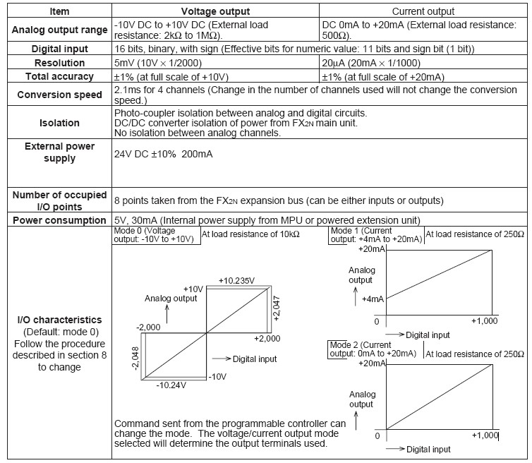
• The FX2N-4DA analog special function block has four output channels. The output channels take a digital value and output an equivalent analog signal. This is called a D/A conversion. The FX2N-4DA has maximum resolution of 12 bits.
• The selection of voltage or current based input/output is by user wiring. Analog ranges of -10 to 10V DC (resolution:5mV), and/or 0 to 20mA (resolution: 20mA) maybe selected independently for each channel.
• Data transfer between the FX2N-4DA and the FX2N main unit is by buffer memory exchange. There are 32 buffer memories (each of 16 bits) in the FX2N-4DA.
• The FX2N-4DA occupies 8 points of I/O on the FX2N expansion bus. The 8 points can be allocated from either inputs or outputs. The FX2N-4DA draws 30mA from the 5V rail of the FX2N main unit or powered extension unit.
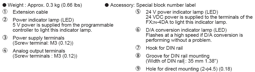
EXTERNAL DIMENSIONS AND PARTS of Mitsubishi FX2N-4DA
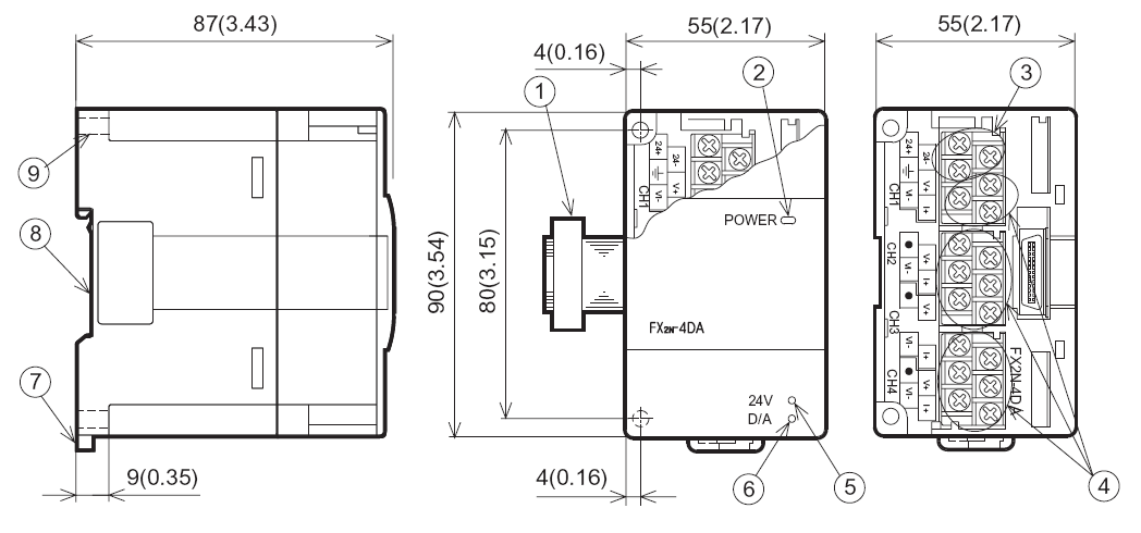
INSTALLATION AND WIRING of Mitsubishi PLC Analogue output module FX2N-4DA
VICONNECTION TO PROGRAMMABLE CONTROLLER of FX2N-4DA
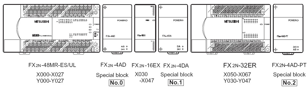
Various special blocks controlled by the FROM/TO commands, such as the analog input blocks high-speed counter blocks, etc. can be connected to the FX2N programmable controller (MPU), or connected to the right side of the other extension blocks or units. Up to eight special blocks can be connected to a single MPU in the numeric order of No. 0 to No. 7.
WIRING of Mitsubishi PLC Analogue output module FX2N-4DA:
The terminal layout shown below may differ from the actual layout. For the correct terminal layout, refer to
section 2 External Dimensions and Parts.
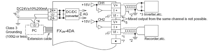
*1: Use a twisted pair shielded cable for the analog output. This cable should be wired away from power lines or any other lines which could induce noise.
*2: Apply 1-point grounding at the load side of the output cable (class 3 grounding: 100W or less).
*3: If electrical noise or a voltage ripple exists at the output, connect a smoothing capacitor of 0.1 to 0.47mF, 25V.
*4: Connect the terminal on the FX2N-4DA with the terminal on the MPU of the programmable controller.
*5: Shorting the voltage output terminal or connecting the current output load to the voltage output terminal may damage the FX2N-4DA.
*6: The 24V DC service power of the programmable controller can also be used.
*7: Do not connect any unit to the unused terminal
SPECIFICATIONS of Mitsubishi PLC Analogue output module FX2N-4DA
ENVIRONMENTAL SPECIFICATIONS of FX2N-4DA
| Item | Specification |
| Environmental specifications (excluding following) | Same as those for the FX2N main unit |
| Dielectric withstand voltage | 500V AC, 1min (between all terminals and ground) |
PERFORMANCE SPECIFICATIONS of FX2N-4DA
ALLOCATION OF BUFFER MEMORIES (BFM) of Mitsubishi FX2N-4DA
Data is transmitted between the FX2N-4DA and the MPU via buffer memories (16-bit 32-point RAM).
Buffer memories marked “W” can be written to using the T0 instruction in the MPU.
The status of BFM #0, #5, and #21, (marked E) will be written to EEPROM, therefore the set values will be retained even after turning off the power.
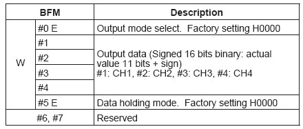
1 [BFM #0] Output mode select: The value of BFM #0 switches the analog output between voltage and current on each channel. It takes the form of a 4 digit hexadecimal number. The first digit will be the command for channel 1 (CH1), and the second digit for channel 2 (CH2) etc. The numeric values of these four digits respectively represent the following items:

2 [BFM #1, #2, #3 and #4]: Output data channels CH1, CH2, CH3, and CH4
BFM #1: Output data of CH1 (Initial value: 0) BFM #2: Output data of CH2 (Initial value: 0)
BFM #3: Output data of CH3 (Initial value: 0) BFM #4: Output data of CH4 (Initial value: 0)
3 [BFM #5]: Data holding mode: While the programmable controller is in the STOP mode, the last output value in the RUN mode will be held. To reset the value to the offset value, write the hexadecimal value in BFM #5 as follows:

In addition to the above functions, the buffer memories can adjust the I/O characteristics of the FX2N-4DA, and report
the status of the FX2N-4DA to the programmable controller.
Buffer memories marked “W” can be written to using the TO instruction in the MPU.The status of BFM #0, #5, and #21, (marked
E) will be written to EEPROM, therefore the set values will be retained even after turning off the power.
*1:Offset data: Actual analog output value when corresponding output data (BFM #1 through #4) is 0
*2:Gain data: Actual analog output value when corresponding output data (BFM #1 through #4) is +1,000
*3: When current output mode 1 (+4 mA to +20 mA) is set, the offset data will be automatically set to +4,000 and the gain
data to +20,000. When the current output mode 2 (0 mA to +20 mA) is set, the offset data will be automatically set to 0 and the gain data to +20,000.
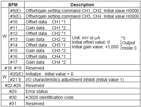
4 [BFM #8 and #9] Offset/gain setting command: Changes offset and gain values of channels CH1 through CH4 by writing 1 to the corresponding Hex digits of BFM #8 or #9. The current values will be valid until this command is output.

5 [BFM #10 through #17] Offset/gain data: The offset and gain values are changed by writing new data to BFM #10 through #17. The units of the data to be written is mV or mA. The data should be written and then BFM #8 and #9 set. Note that the data value will be rounded down to the nearest 5mV or 20mA.
6 [BFM #20] Initialize: When K1 is written in BFM #20, all values will be initialized to the factory-settings.(Note that the BFM #20 data will override the BFM #21 data.) This initialize function is convenient if you have an error in adjustment.
7 [BFM #21] I/O characteristics adjustment inhibit: Setting BFM #21 to 2 inhibits the user from inadvertent adjustment of I/O characteristics. The adjustment inhibit function, once set, will be valid until the Permit command (BFM #21=1) is set. The initial value is 1 (Permit). The set value will be retained even after power-off.
8 [BFM #29] Error status: When an error occurs, use the FROM command to read out the details of the error.

9 [BFM #30]The identification code for a special block is read using the FROM command.The identification code for the FX2N-4DA unit is K3020.The MPU can use this facility in the program to identify the special block before commencing any data transfer from and to the special block.
Note of Mitsubishi PLC Analogue output module FX2N-4DA:
BFM #’s marked E/(E).
• Values of BFM #0, #5, and #21, (marked E) are stored in EEPROM memory of the FX2N-4DA. BFM #10 to #17 are copied to EEPROM when the gain/offset setting command BFM #8, #9 is used. Also, BFM #20 causes resetting of the EEPROM memory. The EEPROM has a life of about 10,000 cycles (changes), so do not use programs which frequently change these BFMs.
• A mode change of BFM #0 automatically involves a change of the corresponding offset and gain values. Because of the time needed to write the new values to the internal EEPROM memory, a delay of 3 s is required between instructions changing BFM #0 and instructions writing to the corresponding BFM #10 through BFM #17.
Therefore, a delay timer should be used before writing to BFM #10 through #17.
OPERATION AND PROGRAM EXAMPLES of Mitsubishi FX2N-4DA
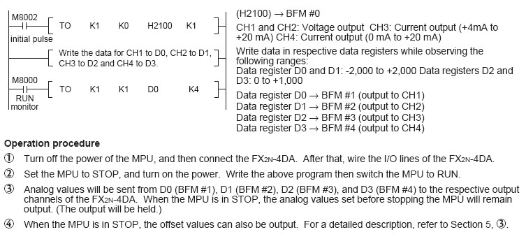
If the factory-set I/O characteristics are not changed and the status information is not used, you can operate the FX2N-4DA using the following simple program. For the FROM and TO commands, refer to the FX Programming Manual.
CH1 and CH2: Voltage output mode (-10 V to +10 V)
CH3: Current output mode (+4 mA to +20 mA)
CH4: Current output mode (0 mA to +20 mA)
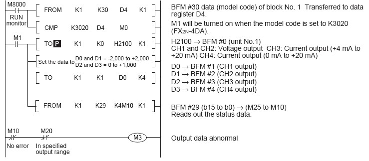
Program example of Mitsubishi FX2N-4DA
For the following program, CH1 and CH2 of the FX2N-4DA connected at special block position No. 1 are used as
voltage output channels, CH3 as a current output channel (+4 mA to +20 mA), and CH4 as a current output channel (0
mA to +20 mA). When the MPU is in STOP, the output will be held. In addition, the status information is used.
Our company (Kollewin Technology CO., Limited) have a new product, named FX2N-4DA.
It is 100% compatible with Mitsubishi original FX2N-4DA.
USER'S MUNUAL PDF of Mitsubishi analogue module FX2N-4DA
Mitsubishi FX_PLC_USER'S Manual FX2N-4DA
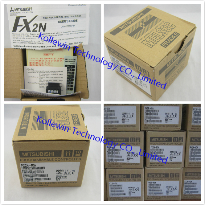
Pictures of our compatible Mitsubishi FX2N-4DA:

More Mitsubishi PLC expansion input & output modules we can supply
| Model | Specification |
| FX2N-8EX | 8 DC input expansion module |
| FX2N-8EYR | 8 relay output expansion module |
| FX2N-8EYT | 8 DC output expansion module |
| FX2N-8ER | 4 input,8 relay output expansion module |
| FX2N-16EX | 16 DC input expansion module |
| FX2N-16EYR | 16 relay output expansion module |
| FX2N-16EYT | 16 DC output expansion module |
| FX2N-2AD | 2 channel analog input 0-10V DC, 0-5V DC, 4-20mA |
| FX2N-2DA | 2 channel analog output 0-10V DC, 0-5V DC, 4-20mA |
| FX2N-4AD | 4 channel analog input -10-10V DC, 4-20mA |
| FX2N-4DA | 4 channel analog output -10-10V DC, 4-20mA |
| FX2N-4AD-PT | 4 channel temperature input PT100 |
| FX2N-4AD-TC | 4 channel temperature input thermocouple(K,J) |
| FX2N-1PG-E | Pulse output positioning module |
| FX0N-3A | 2 channel analog input, 1 channel analog output module |
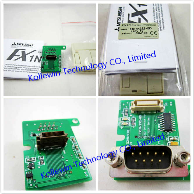
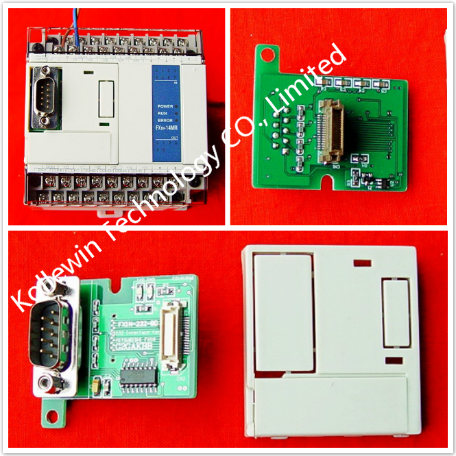
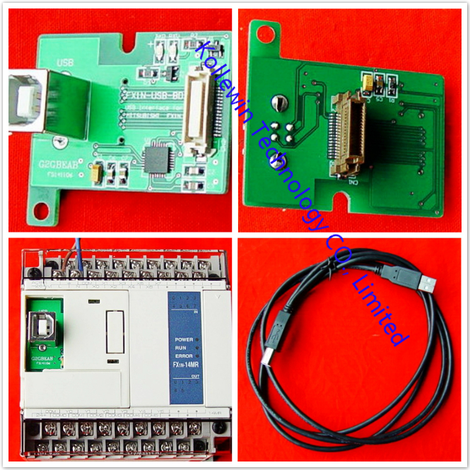
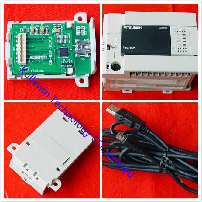
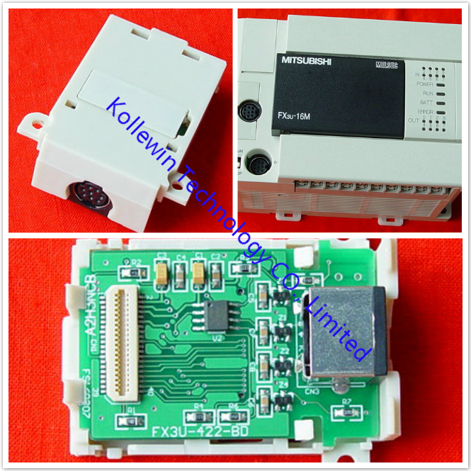
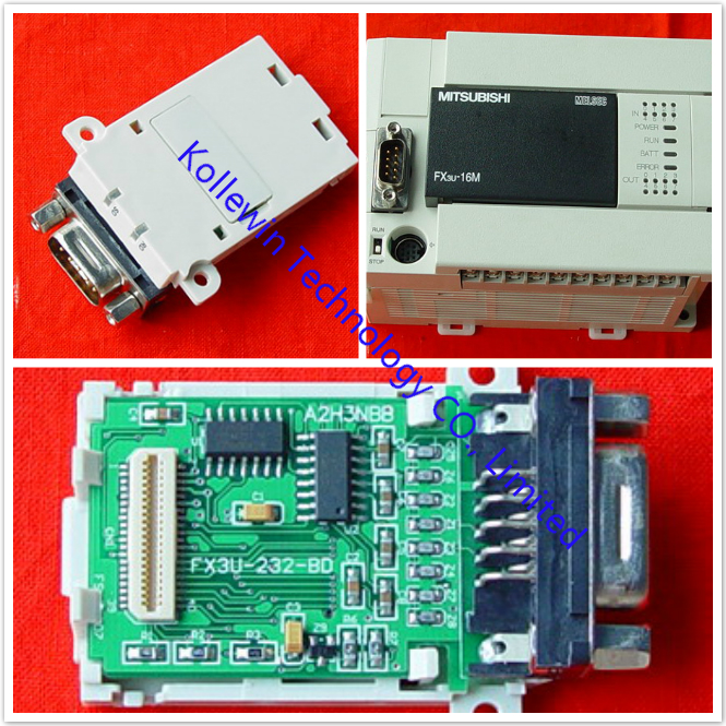
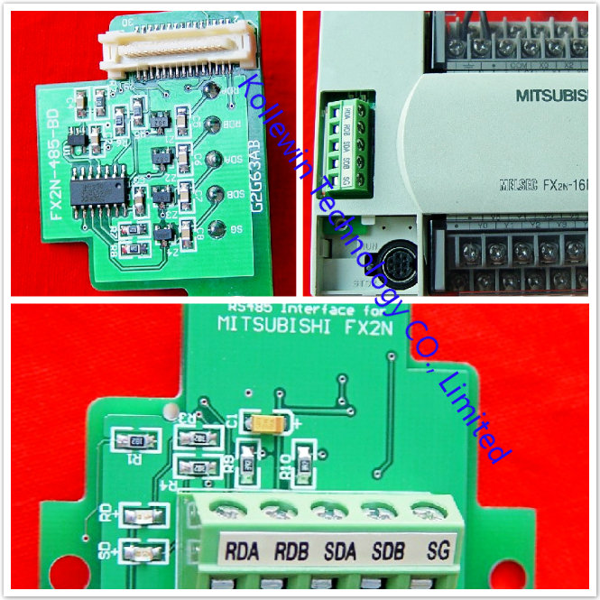
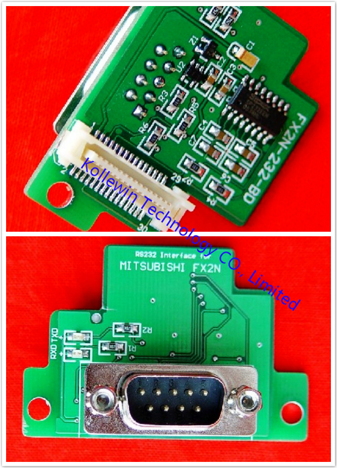
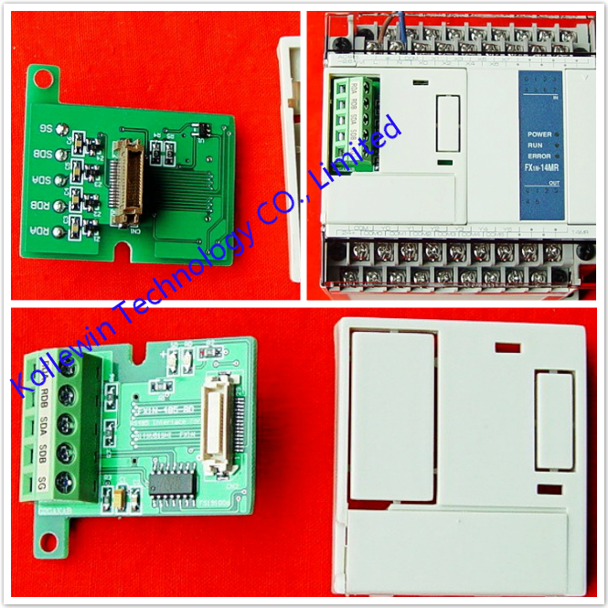
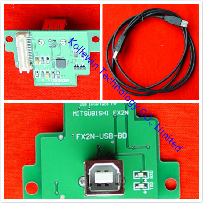
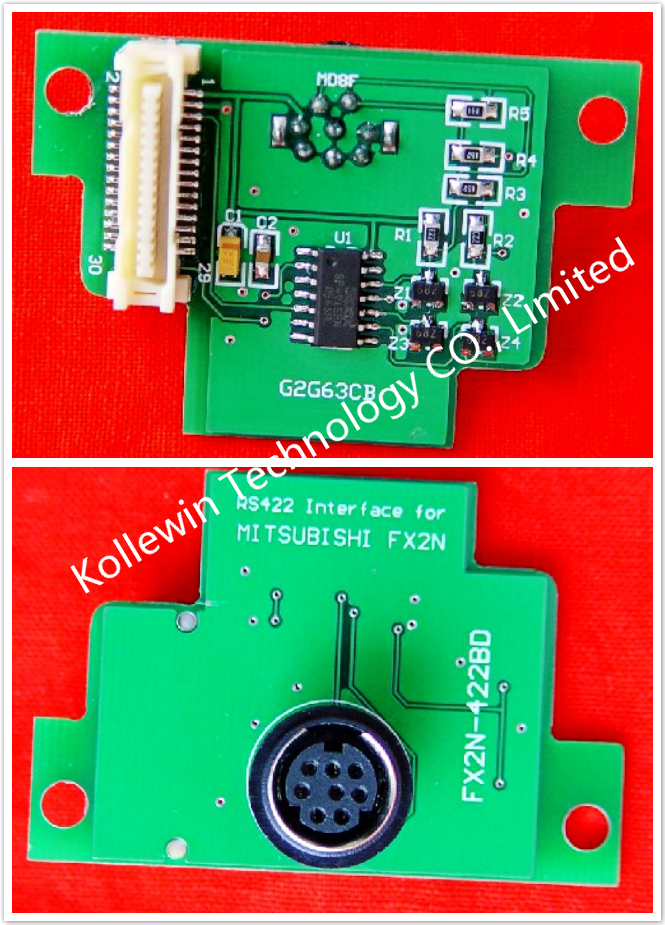
More communication boards, please click below links:
More pictures of communication board for your reference:


Request for price, please feel free to contact me for any question!
Contact person: Miss Nancy
E-mail: nancy@kollewin.com
Tel: +86-0755-26898905-8006
Website: www.kollewin.com
Recent Comments