Mitsubishi FX3U-USB-BD FX3U Communication Board
Introduction to Mitsubishi FX3U-USB-BD
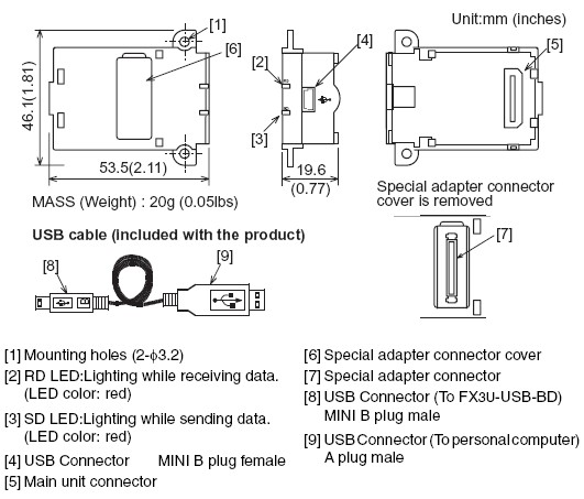
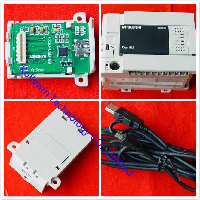
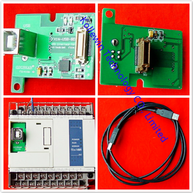
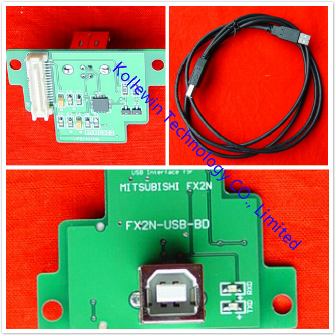
The FX3U-USB-BD board (hereinafter called USB-BD) is a function extension board for USB communication equipped with an USB port (MINI B plug, female).By connecting the USB-BD and a personal computer, program transfer to a PLC main unit and monitoring can be performed.
1.1 Incorporated Items of Mitsubishi FX3U-USB-BD
Check if the following product and items are included in the package:
| Product | USB communication expansion board FX3U-USB-BD | 1 |
|
Included items |
M3 tapping screws USB driver software (CD-ROM) USB cable (3m (118.1")) User's Manual (this manual) |
2 1 1 1 |
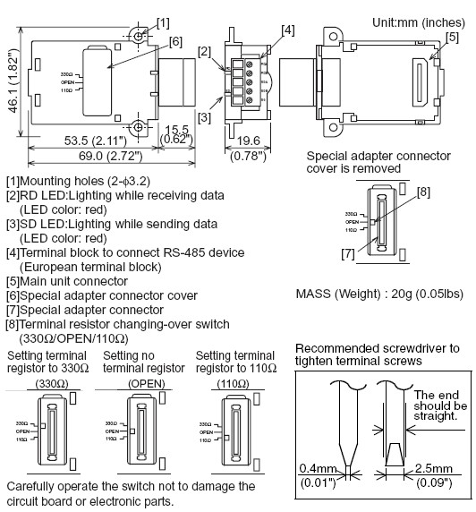
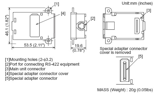
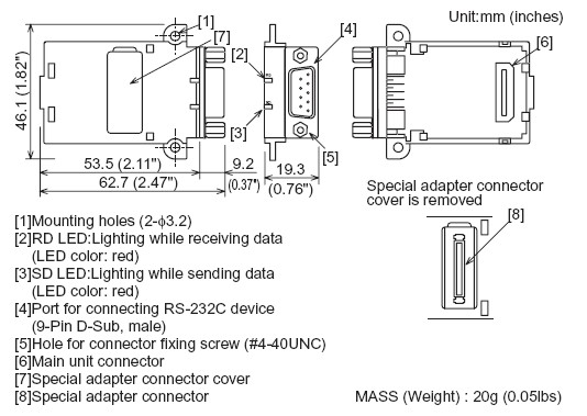
1.2 External Dimensions and Part Names of Mitsubishi FX3U-USB-BD
Installation of Mitsubishi FX3U-USB-BD
• Cut off all phases of the power source externally before starting the installation or wiring work, thus avoiding electric shock or damages to the product.
• Use the product in the environment within the general specifications described in PLC main unit manual (Hardware Edition).
Never use the product in areas with dust, oily smoke, conductive dusts, corrosive gas (salt air, Cl2, H2S, NH3, SO2, or NO2), flammable gas, vibrations or impacts, or expose it to high temperature, condensation, or wind and rain.If the product is used in such a place described above, electrical shock, fire,malfunction, damage, or deterioration may be caused.
• Use screwdrivers carefully when performing installation work, thus avoiding accident or product damage.
• When drilling screw holes or wiring, cutting chips or wire chips should not enter ventilation slits.Such an accident may cause fire, failure or malfunction.
• Do not touch the conductive parts of the product directly, thus avoiding failure or malfunction.
• Fix the expansion board securely to the specified connector. Incorrect connection may cause malfunction.
The following explains the installation method to FX3U/FX3UC Series PLC (FX3U Series PLC is used for the following example).
For removing and installing details, refer to the PLC main unit manual.
However, FX3UC Series PLC manual is only available in Japanese.
2.1 Installation Method of Mitsubishi FX3U-USB-BD
• Refer to the procedure 2) for configuring a new system.
• Refer to the procedure 1) for adding product to an existing system.
1) Power off the PLC.
Disconnect all the cables connected to the PLC.
Dismount the PLC from the DIN rail.
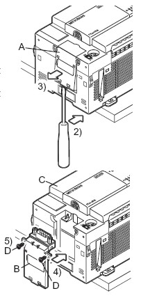
2) Using a flat blade screwdriver as shown in the right figure, lift the little dummy expansion board cover (right fig. A). Do not damage the circuit board or electronic parts.
3) Remove the dummy expansion board cover (right fig. A) in a parallel motion away from the main unit.
4) Make sure the expansion board (right fig. B) is in parallel with the main unit (right fig. C) and fix it to the expansion board connector.
5) Fix the expansion board (right fig. B) to the main unit using the M3 tapping screws of the provided (right fig. D).
Tighten to a torque: 0.3 to 0.6 N⋅m
Specification of Mitsubishi FX3U-USB-BD
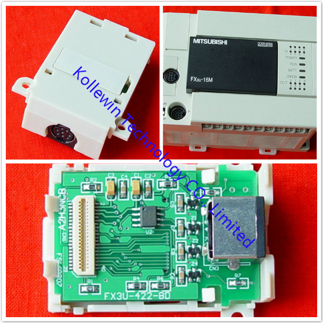
3.1 Applicable PLC of Mitsubishi FX3U-USB-BD
| Model name | Applicability |
| FX3U Series PLC | Ver.2.00 or later (from the first product) |
| FX3UC Series PLC | Ver.1.00 or later |
Only one function expansion board can be used for one main unit.
Two or more FX3U-USB-BD cannot be used, or other expansion boards such as FX3U-422-BD or FX3U-485-BD cannot be installed/used together with FX3U-USB-BD.
3.2 General Specifications of Mitsubishi FX3U-USB-BD
General specifications are equivalent to the PLC main unit.
However, please don't perform any dielectric withstand voltage test and insulation resistance test to this product.
3.3 Power Supply Specification of Mitsubishi FX3U-USB-BD
| Item | Specification |
| Current consumption |
15mA / DC 5V (supplied by DC 5V power of main unit) 30mA / DC 5V (supplied by USB connector of personal computer) |
3.4 Communication Specifications of Mitsubishi FX3U-USB-BD
| Item | Specification |
|
Transmission standard |
USB2.0 (For full speed) |
| Isolation |
Photocoupler isolation (Between communication line and CPU) |
|
Maximum transmission distance |
5m (196.9") at most (Included cable is 3m(118.1").) |
| Baud Rate | 9600/19200/38400/57600/115200 bps |
| Port | USB (MINI B plug female) |
3.5 System Requirements of Mitsubishi FX3U-USB-BD

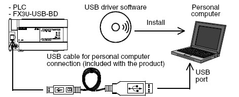
System Configuration of Mitsubishi FX3U-USB-BD
Connected equipment and connected cable
Connecting Procedure of Mitsubishi FX3U-USB-BD
1) Power off the PLC.
2) Connect the USB (MINI B plug male) connector of the USB cable to the FX3U-USB-BD.
3) Connect the USB (A plug male) connector of the USB cable to the personal computer.
4) Turn ON the power supply of the PLC.
5) Turn ON the power supply of the personal computer.
6. Driver Installation
Procedure for installing the driver is explained below.
Windows XP installation follows.
• Windows 98, Windows 98SE, Windows Millennium Edition, and Windows2000, the installation method will vary.
Installation of the driver is canceled during the following process, the installation is not carried out correctly.
If the installation is canceled, uninstall the driver and install again.
Please refer to Chapter 8 for instructions on uninstalling the driver.
Please install the driver with the following procedure.
1)When the USB cable is connected to the personal computer, the following screen is displayed.When the USB cable is connected to the personal computer, the following screen is displayed.

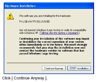
2) The following screen is displayed. (Only in Windows XP)
3) The following screen is displayed.
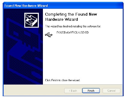
Click [ Finish ].
The installation of the USB driver software will finish.
- If Windows 98, Windows 98SE or Windows Millennium Edition is used,installation of the USB Serial Port software begins, and ends automatically.
The CD-ROM can be removed from the personal computer at this time.
- If using Windows 2000 or Windows XP, proceed to step 4).
4) The following screen is displayed.
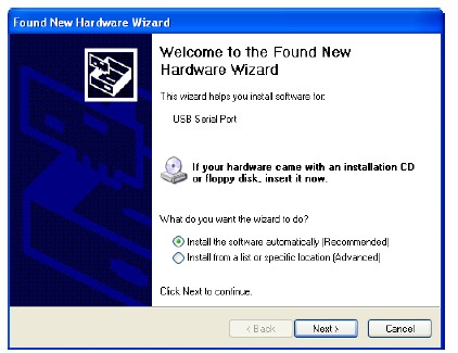
Click [ Next > ].
The installation of the USB Serial Port software will begin.
- If using Windows 2000, a screen to select the location of the installation files is displayed.
Please select the CD-ROM drive.
5) The screen of 2) is displayed. (Only in Windows XP)
Click [ Continue Anyway ].
6) The following screen is displayed.
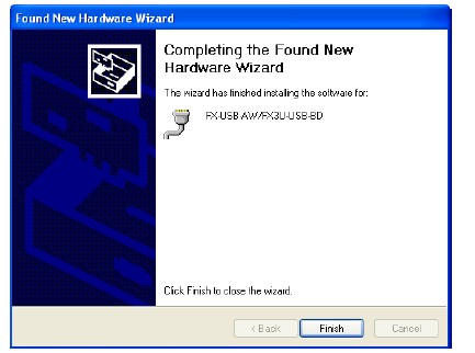
Click [ Finish ].
The installation of the USB Serial Port software will finish.
The CD-ROM (USB driver software) can be removed from the personal computer at this time.
Our company (Kollewin Technology CO., Limited) have a new product, named FX3U-USB-BD.
It is 100% compatible with Mitsubishi original FX3U-USB-BD.
Part#: FX3U-USB-BD
The unit price is USD40.69/pc ![]()
USER'S MUNUAL PDF of communication board FX3U-USB-BD:
USB COMMUNICATION BOARD FX3U-USB-BD
Specification of communication board FX3U-USB-BD:
| Product Name | Communication Board |
| Fit | for Mitsubishi FX3U PLC |
| Model NO. | FX3U-USB-BD |
| Transmission standard | USB2.0 (For full speed) |
| Voltage | DC 5V |
| Current consumption |
15mA / DC 5V (supplied by DC 5V power of main unit) 30mA / DC 5V (supplied by USB connector of personal computer) |
| Max.Transmission Distance | 5m (196.9") at most (Included cable is 3m(118.1").) |
| LED Indicators | SD, RD |
| Communication Method | Half-duplex |
| Isolation |
Photocoupler isolation (Between communication line and CPU) |
| Material | Plastic, Metal |
| Net Weight | 20g |
| Port | USB Connector(MINI B plug female) |
| Package Content | 2 x M3 tapping screws |
| 1 x USB driver software (CD-ROM) | |
| 1 x USB cable (3m (118.1")) | |
| 1 x User's Manual (this manual) |
Description of communication board FX3U-USB-BD:
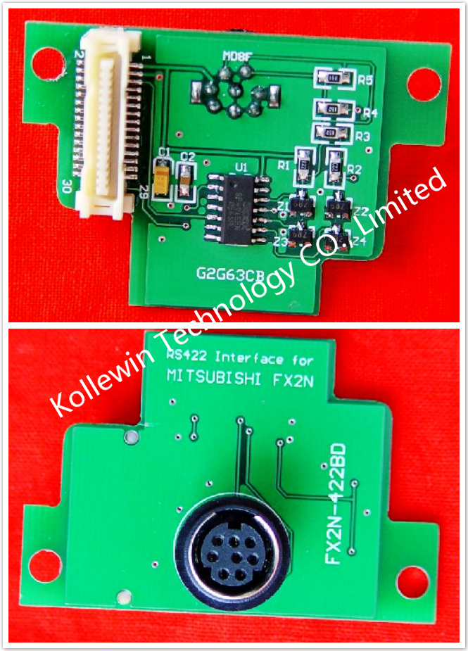
- This is a USB communication expansion board FX3U-USB-BD. FX3U-USB-BD is an expansion board equipped with an European temial black for USB communication.
- The FX3U-USB-BD exchange data with USB devices.
- FX3U-USB-BD:USB Board for FX3U PLC, anti-static electricity and surging protection.
- This is OEM product, not Mitsubishi original part.
More communication boards, please click below links:
More pictures of communication board


Please feel free to contact me for any question!
Contact person: Miss Nancy
E-mail: nancy@kollewin.com
Tel: +86-0755-26898905-8006
Website: www.kollewin.com

Recent Comments