Introduction to 6ES7331-7KF02-0AB0
SIMATIC S7-300, ANALOG INPUT SM 331, OPTICALLY ISOLATED, 8AI, RESOLUTION 9/12/14 BITS, U/I/THERMOCOUPLE/RESISTANCE INTERRUPT, DIAGNOSTICS; 1X20PIN REMOVE/INSERT W. BACKPLANE BUS
Properties of 6ES7331-7KF02-0AB0
● 8 inputs in 4 channel groups
● Programmable measurement type at each channel group
– Voltage
– Current
– Resistance
– Temperature
● Programmable resolution at each channel group (9/12/14 bits + sign)
● Any measuring range selection per channel group
● Programmable diagnostics and diagnostic interrupt
● Programmable limit value monitoring for 2 channels
● Programmable hardware interrupt when limit is exceeded
● Electrically isolated to CPU and load voltage (not for 2-wire transducers)
Resolution
The measured value resolution is directly proportional to the selected integration time, that is, the measured value resolution increases in proportion to length of the integration time at the analog input channel.
Diagnostics
For information on diagnostics messages at the "group diagnostics" parameter, refer to chapter Diagnostic messages of analog input modules.
Hardware interrupts
Hardware interrupts for channel groups 0 and 1 can be programmed in STEP 7.
However,set a hardware interrupt only for the first channel of a channel group, that is, either at channel 0, or at channel 2.
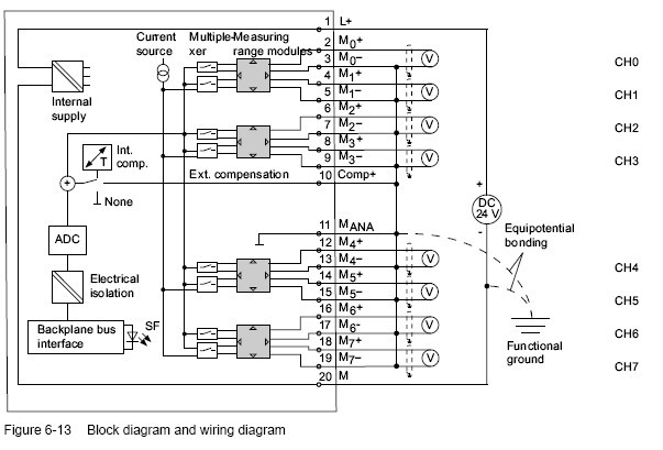
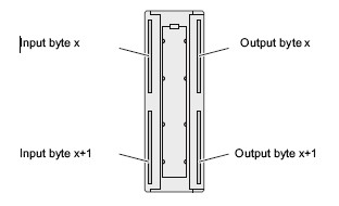
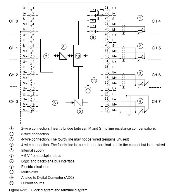
Terminal assignment
The diagrams below show various wiring options The input impedance depends on the
setting of the measuring range module, see table Measurement types and ranges.
Wiring: Voltage measurement
Measuring range module settings of 6ES7331-7KF02-0AB0
|
Measuring range
|
Measuring range module setting
|
|
± 80 mV
|
A
|
|
± 250 mV
|
|
|
± 500 mV
|
|
|
± 1,000 mV
|
|
|
± 2.5 V
|
B
|
|
± 5 V
|
|
|
1 V to 5 V
|
|
|
± 10 V
|
|
Wiring: 2-wire and 4-wire transducers for current measurement
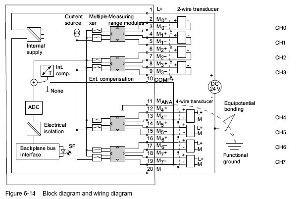
Note
The interconnection between MANA and M- (terminals 11, 13, 15, 17, 19) is not required when
using grounded 4-wire transducers with non-isolated supply.
Measuring range module settings of 6ES7331-7KF02-0AB0
|
Measuring range
|
|
Measuring range module setting
|
|
2-wire transducer
|
4 mA to 20 mA
|
D
|
|
4-wire transducer
|
± 3.2 mA
|
C
|
|
|
± 10 mA
|
|
|
|
0 mA to 20 mA
|
|
|
|
4 mA to 20 mA
|
|
|
|
± 20 mA
|
|
CAUTION
Measuring range module in "Current" position
Any voltage measurement will destroy the measuring range module if "current" measuring mode is set.
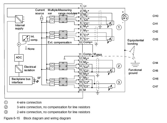
Wiring: 2-, 3- and 4-wire connection of resistance transducers or thermoresistors
Measuring range module settings
|
Measuring range
|
|
Measuring range module setting
|
|
150 Ω
|
|
A
|
|
300 Ω
|
|
|
|
600 Ω
|
|
|
|
Thermoresistor (linear, 4-wire connection)
|
Pt 100 Klima
|
A
|
|
(temperature measurement) RTD-4L
|
Ni 100 Klima
|
|
|
|
Pt 100 Standard
|
|
|
|
Ni 100 Standard
|
|
Note
• "Resistance measurement" is only available at one channel per group. The "2nd" channel of the group is used accordingly for current measuring mode (IC). The "1st" channel of the group returns the measured value. The "2nd" channel of the group is assigned the default overflow value "7FFFH."
• There is no compensation for power resistors for "2- and 3-wire connections".
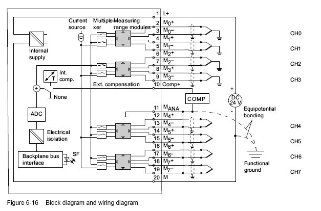
Wiring: Thermocouples with external compensation
Insert a bridge between Comp+ and MANA when using the internal compensation.
Measuring range module settings
|
Measuring range
|
|
Measuring range module setting
|
|
Thermocouple TC-I
|
Type N [NiCrSi-NiSi]
|
A
|
|
(internal comparison) (thermal
|
Type E [NiCr-CuNi]
|
|
|
voltage measurement)
|
Type J [Fe-CuNi]
|
|
|
Linearization is ignored
|
Type K [NiCr-Ni]
|
|
|
Thermocouple TC-E
|
Type L [Fe-CuNi]
|
|
|
(external comparison)
|
|
|
|
(thermovoltage measurement)
|
|
|
|
Linearization is ignored
|
|
|
|
Thermocouple
|
Type N [NiCrSi-NiSi]
|
A
|
|
(linear, internal comparison)
|
Type E [NiCr-CuNi]
|
|
|
(temperature measurement) TCIL
|
Type J [Fe-CuNi]
|
|
|
Thermocouple
|
Type K [NiCr-Ni]
|
|
|
(linear, external comparison)
|
Type L [Fe-CuNi]
|
|
|
(temperature measurement) TCEL
|
|
|
Note
• An interconnection of M- and MANA is prohibited when using grounded thermocouples. In
this case, you must ensure that low-resistance equipotential bonding is in place so that
the permitted common-mode voltage is not exceeded.
• Interconnect M- and MANA when using non-grounded thermocouples
Technical specifications of Analog input module 6ES7331-7KF02-0AB0
|
SIMATIC S7-300, ANALOG INPUT SM 331, OPTICALLY ISOLATED, 8AI, RESOLUTION 9/12/14 BITS, U/I/THERMOCOUPLE/RESISTANCE INTERRUPT, DIAGNOSTICS; 1X20PIN REMOVE/INSERT W. BACKPLANE BUS
|
|
|
|
Supply voltage
|
|
Load voltage L+
|
|
Rated value (DC)
|
24 V
|
|
Reverse polarity protection
|
Yes
|
|
Input current
|
|
from load voltage L+ (without load), max.
|
200 mA
|
|
from backplane bus 5 V DC, max.
|
50 mA
|
|
Power losses
|
|
Power loss, typ.
|
1 W
|
|
Analog inputs
|
|
Number of analog inputs
|
8
|
|
Number of analog inputs for resistance measurement
|
4
|
|
permissible input voltage for voltage input (destruction limit), max.
|
20 V; continuous; 75 V for max. 1 s (mark to space ratio 1:20)
|
|
permissible input current for current input (destruction limit), max.
|
40 mA
|
|
Input ranges
|
|
Voltage
|
Yes
|
|
Current
|
Yes
|
|
Thermocouple
|
Yes
|
|
Resistance thermometer
|
Yes
|
|
Resistance
|
Yes
|
|
Input ranges (rated values), voltages
|
|
0 to +10 V
|
No
|
|
1 to 5 V
|
Yes
|
|
Input resistance (1 to 5 V)
|
100 kΩ
|
|
1 to 10 V
|
No
|
|
-1 V to +1 V
|
Yes
|
|
Input resistance (-1 V to +1 V)
|
10 MΩ
|
|
-10 V to +10 V
|
Yes
|
|
Input resistance (-10 V to +10 V)
|
100 kΩ
|
|
-2.5 V to +2.5 V
|
Yes
|
|
Input resistance (-2.5 V to +2.5 V)
|
100 kΩ
|
|
-250 mV to +250 mV
|
Yes
|
|
Input resistance (-250 mV to +250 mV)
|
10 MΩ
|
|
-5 V to +5 V
|
Yes
|
|
Input resistance (-5 V to +5 V)
|
100 kΩ
|
|
-50 mV to +50 mV
|
No
|
|
-500 mV to +500 mV
|
Yes
|
|
Input resistance (-500 mV to +500 mV)
|
10 MΩ
|
|
-80 mV to +80 mV
|
Yes
|
|
Input resistance (-80 mV to +80 mV)
|
10 MΩ
|
|
Input ranges (rated values), currents
|
|
0 to 20 mA
|
Yes
|
|
Input resistance (0 to 20 mA)
|
25 Ω
|
|
-10 to +10 mA
|
Yes
|
|
Input resistance (-10 to +10 mA)
|
25 Ω
|
|
-20 to +20 mA
|
Yes
|
|
Input resistance (-20 to +20 mA)
|
25 Ω
|
|
-3.2 to +3.2 mA
|
Yes
|
|
Input resistance (-3.2 to +3.2 mA)
|
25 Ω
|
|
4 to 20 mA
|
Yes
|
|
Input resistance (4 to 20 mA)
|
25 Ω
|
|
Input ranges (rated values), thermoelements
|
|
Type B
|
No
|
|
Type E
|
Yes
|
|
Input resistance (Type E)
|
10 MΩ
|
|
Type J
|
Yes
|
|
Input resistance (type J)
|
10 MΩ
|
|
Type K
|
Yes
|
|
Input resistance (Type K)
|
10 MΩ
|
|
Type L
|
Yes
|
|
Input resistance (Type L)
|
10 MΩ
|
|
Type N
|
Yes
|
|
Input resistance (Type N)
|
10 MΩ
|
|
Type R
|
No
|
|
Type S
|
No
|
|
Type T
|
No
|
|
Type U
|
No
|
|
Type TXK/TXK(L) to GOST
|
No
|
|
Input ranges (rated values), resistance thermometers
|
|
Cu 10
|
No
|
|
Ni 100
|
Yes; Standard
|
|
Input resistance (Ni 100)
|
10 MΩ
|
|
Ni 1000
|
No
|
|
LG-Ni 1000
|
No
|
|
Ni 120
|
No
|
|
Ni 200
|
No
|
|
Ni 500
|
No
|
|
Pt 100
|
Yes; Standard
|
|
Input resistance (Pt 100)
|
10 MΩ
|
|
Pt 1000
|
No
|
|
Pt 200
|
No
|
|
Pt 500
|
No
|
|
Input ranges (rated values), resistors
|
|
0 to 150 ohms
|
Yes
|
|
Input resistance (0 to 150 ohms)
|
10 MΩ
|
|
0 to 300 ohms
|
Yes
|
|
Input resistance (0 to 300 ohms)
|
10 MΩ
|
|
0 to 600 ohms
|
Yes
|
|
Input resistance (0 to 600 ohms)
|
10 MΩ
|
|
0 to 6000 ohms
|
No
|
|
Thermocouple (TC)
|
|
for thermocouples
|
Type E, J, K, L, N
|
|
Temperature compensation
|
|
Parameterizable
|
Yes
|
|
internal temperature compensation
|
Yes
|
|
external temperature compensation with compensations socket
|
Yes
|
|
Resistance thermometer (RTD)
|
|
Characteristic linearization
|
|
for resistance thermometer
|
Pt100 (standard, climatic range), Ni100 (standard, climatic range)
|
|
Characteristic linearization
|
|
Parameterizable
|
Yes
|
|
Cable length
|
|
Cable length, shielded, max.
|
200 m; 50 m at 80 mV and thermocouples
|
|
Analog value creation
|
|
Measurement principle
|
integrating
|
|
Integrations and conversion time/ resolution per channel
|
|
Resolution with overrange (bit including sign), max.
|
15 bit; Unipolar: 9/12/12/14 bits; bipolar: 9 bits + sign/12 bits + sign/12 bits + sign/14 bits + sign
|
|
Integration time, parameterizable
|
Yes; 2.5/ 16.67/ 20/ 100 ms
|
|
Basic conversion time, ms
|
3 / 17 / 22 /102 ms
|
|
Interference voltage suppression for interference frequency f1 in Hz
|
400 / 60 / 50 / 10 Hz
|
|
Encoder
|
|
Connection of signal encoders
|
|
for current measurement as 2-wire transducer
|
Yes
|
|
for current measurement as 4-wire transducer
|
Yes
|
|
for resistance measurement with 2-conductor connection
|
Yes
|
|
for resistance measurement with 3-conductor connection
|
Yes
|
|
for resistance measurement with 4-conductor connection
|
Yes
|
|
Errors/accuracies
|
|
Operational limit in overall temperature range
|
|
Voltage, relative to input area
|
+/- 1 %; +/-1% (80 mV); +/-0.6% (250 to 1000 mV); +/-0.8% (2.5 to 10 V)
|
|
Current, relative to input area
|
+/- 0,7 %; From 3.2 to 20 mA
|
|
Impedance, relative to input area
|
+/- 0,7 %; 150, 300, 600 Ohm
|
|
Resistance-type thermometer, relative to input area
|
+/- 0,7 %; +/-0.7% (Pt100/ Ni100); +/-0.8% (Pt100 climate)
|
|
Basic error limit (operational limit at 25 °C)
|
|
Voltage, relative to input area
|
+/- 0,6 %; +/-0.4% (250 to 1000 mV); +/-0.6 % (2.5 to 10 mV); +/-0.7 % (80 mV)
|
|
Current, relative to input area
|
+/- 0,5 %; 3.2 to 20 mA
|
|
Impedance, relative to input area
|
+/- 0,5 %; 150, 300, 600 Ohm
|
|
Resistance-type thermometer, relative to input area
|
+/- 0,6 %; +/-0.5% (Pt100/ Ni100); +/-0.6% (Pt100 climate)
|
|
Isochronous mode
|
|
Isochronous operation (application synchronized up to terminal)
|
No
|
|
Interrupts/diagnostics/status information
|
|
Alarms
|
|
Diagnostic alarm
|
Yes; Parameterizable, channels 0 and 2
|
|
Limit value alarm
|
Yes; Parameterizable
|
|
Diagnostic messages
|
|
Diagnostic functions
|
Yes; Parameterizable
|
|
Diagnostic information readable
|
Yes
|
|
Diagnostics
|
Yes
|
|
Diagnostics indication LED
|
|
Group error SF (red)
|
Yes
|
|
Galvanic isolation
|
|
Galvanic isolation analog inputs
|
|
between the channels
|
No
|
|
between the channels and the backplane bus
|
Yes
|
|
Isolation
|
|
Isolation checked with
|
500 V DC
|
|
Connection method
|
|
required front connector
|
20-pin
|
|
Dimensions
|
|
Width
|
40 mm
|
|
Height
|
125 mm
|
|
Depth
|
120 mm
|
|
Weight
|
|
Weight, approx.
|
250 g
|
Measurement types and ranges
Introduction
Module SM 331; AI 8 x 12 Bit has measuring range modules
The measurement type and range is configured at the "measuring range" parameter in STEP 7.
The default setting of the module is "voltage" measurement with "± 10V" range. You can use these default settings without having to program the SM 331; AI 8 x 12 Bit in STEP 7.
Measuring range modules
You may have to change the position of the measuring range modules to suit the measurement type and range (see the chapter Setting the measuring types and ranges of analog input channels ).
The necessary settings are also available on the module's imprint. Mark the position of the measuring range module on the front door.
Additional information on SM 331; AI 8 x 12 Bit
Unused channels
As certain programmed inputs may remain unused due to the channel group configuration,make allowances for the special features of these inputs outlined below in order to be able to use the diagnostics functions at these used channels:
● Voltage measurement (except 1 V to 5V) and for thermocouples: Short-circuit unused channels and connect these with MANA. This optimizes interference immunity of the analog input module. Set the "disabled" value at the "measurement type" parameter for unused channels. This setting reduces module cycle times. Also short-circuit the COMP input if this is not used.
● Measuring range 1 V to 5 V: wire the used and unused inputs of the same channel group in parallel.
● Current measurement, 2-wire transducer: There are two options of wiring the channel circuit.
a) Open unused input; channel group diagnostics disabled. If you were to enable diagnostics, the analog module would trigger a single diagnostic interrupt, and light up its SF LED.
b) Loading the unused input using a 1.5 kΩ to 3.3 kΩ resistor. This allows you to enable diagnostics for this channel group.
● Current measurement 4 mA to 20 mA, 4-wire transducer: wire the unused inputs of the same channel group in series.
All channels deactivated
If you disable all input channels of the module and enable diagnostics at the parameters of SM 331; AI 8 x 12 Bit, the module does not report "external auxiliary voltage missing."
Line continuity check for the 4 mA to 20 mA measuring range
If you configured a measuring range of 4 mA to 20 mA, and enabled the line continuity check, the analog input module logs a wire-break event to diagnostics data when the current drops below 3.6 mA.
The module also triggers a diagnostics interrupt if this function is enabled in the program.A wire break can only be signaled by means of the lit SF LED and the diagnostic bytes must be evaluated in the user program if diagnostics interrupts are disabled.
If you configured a measuring range of 4 mA to 20 mA, disabled the line continuity check,and enabled diagnostic interrupts, the module triggers a diagnostic interrupt when the underflow value is reached.
Line continuity check
The line continuity check is designed only for temperature measurements (thermocouples and thermoresistors.)
USER'S manual PDF of 331-7KF02, please refer from Page 370- Page 385:
S7-300 Modules data & USER'S MANUAL
Our company (Kollewin Technology CO., Limited) have a new product,
named 6ES7331-7KF02-0AB0,
it is 100% compatible with Siemens original part.
Part#: 6ES7331-7KF02-0AB0
Unit price:USD367.00/pc 
Description: S7-300 Analog input module
Manufacturer: Kollewin
Approx. Weight: 0.3 Kg
Warranty: 1 year
Origin: China
Here, you need 1 piece of 20pin front connector to connect with 6ES7331-7KF02-0AB0.
Our compatible 6ES7 392-1AJ00-0AA0 can meet your requirements.
6ES7 392-1AJ00-0AA0 @USD10.50/pc
Technical data sheet of our SM 331 6ES7331-7KF02-0AB0
|
Model
|
SM331
8AI
|
|
Product Description
|
8AI;
Full-function temperature measurement modules; Resolution:16bits;
Short-circuit protection ;High immunity;stable
|
|
Power consumption
|
|
·Rate value
|
24V DC
|
|
·From backplane bus current consumption
|
100mA
|
|
·From L+
|
25mA
|
|
·Power loss
|
1W
|
|
The power of transmitter
|
|
|
·Supply current
|
Per channel (Max):60mA
|
|
·short-circuit protection
|
Yes
|
|
Number of analog inputs
|
8
|
|
Cable Length (Shielded)
|
200m
Max.For 80mV:50m
|
|
Input type and input range
|
|
|
·voltage
|
±80mV, ±250mV,
±500mV,±1V, ±2.5V ±5V,1~5V, ±10V
|
|
·current(4wire)
|
±3.2mA, ±10mA, ±20mA, 4~20mA
|
|
·current(2wire)
|
4~20mA
|
|
·tesistance
|
600Ω, 300Ω, 150Ω,
|
|
·thermocouple
|
K,J,N,E,L
|
|
·RTD
|
Pt100,Ni100
|
|
A/D resolution
|
16bits
|
|
Basic conversion time(per channel)
|
0.5ms/12.5ms/25ms/50ms
|
|
Interference frequency suppression
|
400/60/50/10Hz
|
|
Tolerance(Over entire temperature range)
|
|
·Voltage
|
±0.6%
|
|
·Current
|
±0.6%
|
|
·resistance
|
±0.6%
|
|
·temperature
|
±1℃
|
|
Interrupts
|
|
Diagnostic interrupt
|
Per group Yes,Configurable
|
|
Limit-value interrupt
|
Yes,Configurable
|
|
Isolation tested for contact
|
|
·Between channels
|
None
|
|
·Between channels and backplane bu
|
Yes
|
|
Front connector
|
20-pin
|
|
Dimensions(W x H x D)(mm)
|
40×125×120
|
|
Order Number
|
331-7KF02-0AB0
|
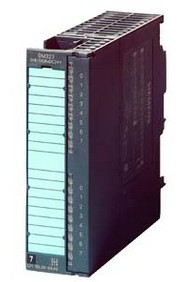
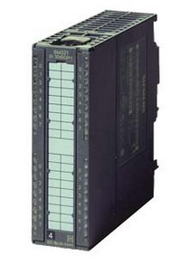
Picture of 6ES7331-7KF02-0AB0

More compatible Siemens S7-200/300 modules we can offer:
|
Model
|
Product Description
|
|
SM7-200 DIGITAL MODULE
|
|
6ES7221-1BH22-0XA0
|
EM221 16 DI 24V DC
|
|
6ES7221-1BL22-0XA0
|
EM221 32 DI 24V DC
|
|
6ES7222-1BF22-0XA0
|
EM222 8DO,DC 24V
|
|
6ES7222-1HF22-0XA0
|
EM222 8DO,relay
|
|
6ES7222-1BH22-0XA0
|
EM222 16 DO 24V DC
|
|
6ES7222-1HH22-0XA0
|
EM222 16 DO RELAY
|
|
6ES7222-1BL22-0XA0
|
EM222 32 DO 24V DC
|
|
6ES7223-1HF22-0XA0
|
EM223 4DI/4DO,DC 24V relay
|
|
6ES7223-1BH22-0XA0
|
EM223 8 DI/ 8 DO 24V DC
|
|
6ES7223-1PH22-0XA0
|
EM223 8 DI 24V DC/8 DO RELAY
|
|
6ES7223-1BL22-0XA0
|
EM223 16 DI/ 16 DO 24V DC
|
|
6ES7223-1PL22-0XA0
|
EM223 16 DI 24V DC/ 16 DO RELAY
|
|
6ES7223-1BF22-0XA0
|
4 DI/4DO,24 VDC
|
|
6ES7221-1BF22-0XA0
|
8 DI,24V DC
|
|
SM7-200 ANALOG MODULE
|
|
6ES7231-0HC22-0XA0
|
EM231 4 AI x 12 Bits
|
|
6ES7231-0HF22-0XA0
|
EM231 8 AI x 12/11 BIT
|
|
6ES7231-7PC22-0XA0
|
EM231 4 RTD
|
|
6ES7231-7PD22-0XA0
|
EM231 4 TC
|
|
6ES7231-7PH22-0XA0
|
EM231 8 TC
|
|
6ES7231-7PL22-0XA0
|
16AI, T/C INPUT MOD, 16BIT
|
|
6ES7231-7PB22-0XA0
|
2AI, RTD INPUT MOD. 16BIT
|
|
6ES7232-0HB22-0XA0
|
EM232 2 AO x 12 Bits
|
|
6ES7232-0HD22-0XA0
|
EM232 4 AO x 12 Bits
|
|
6ES7235-0KD22-0XA0
|
EM235 4 AI/ 1 AO x 12 Bits
|
|
SM7-300 DIGITAL MODULE
|
|
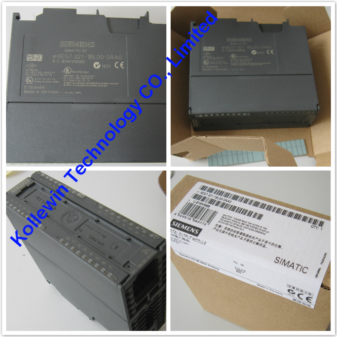
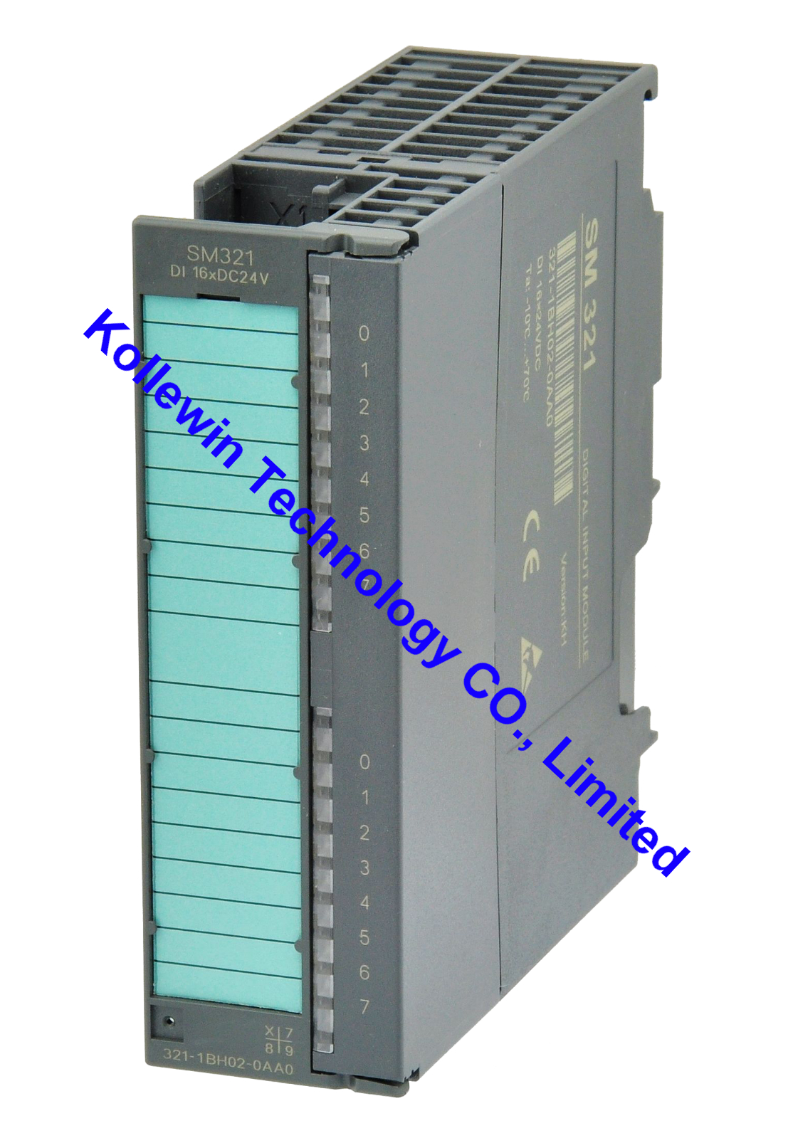
6ES7321-1BH02-0AA0
|
SM321 16 DI 24 VDC
|
|
6ES7321-1FH00-0AA0
|
SM321 16 DI AC 230V
|
|
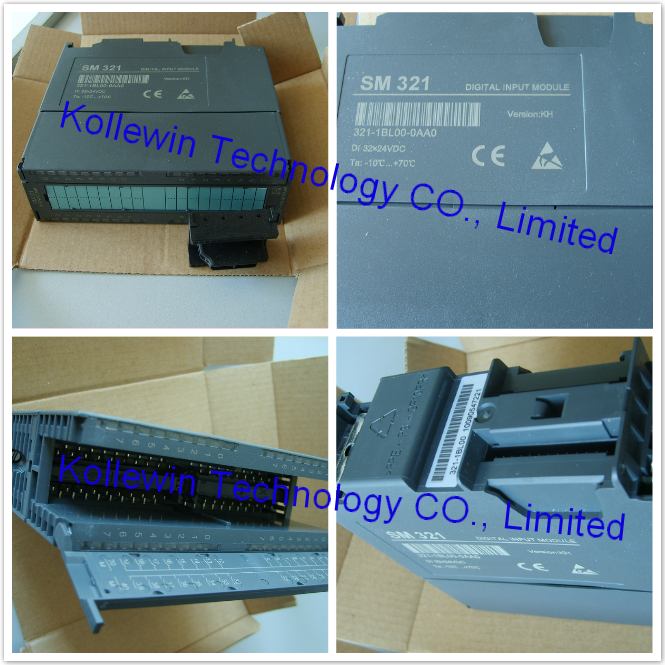
6ES7321-1BL00-0AA0
|
SM321 32 DI 24 VDC
|
|
6ES7322-1BF01-0AA0
|
SM322,8DO,24VDC,2A
|
|
6ES7322-1BH01-0AA0
|
SM322 16 DO 24 VDC/ 0.5A
|
|
6ES7322-1HH01-0AA0
|
SM322 16 DO RELAY
|
|
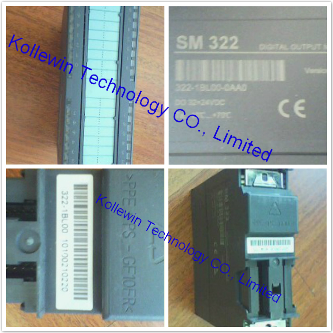
6ES7322-1BL00-0AA0
|
SM322 32 DO 24V DC/0.5A
|
|
6ES7323-1BL00-0AA0
|
SM323 16DI 24V DC/ 16DO 24V DC 0.5A
|
|
SM7-300 ANALOG MODULE
|
|
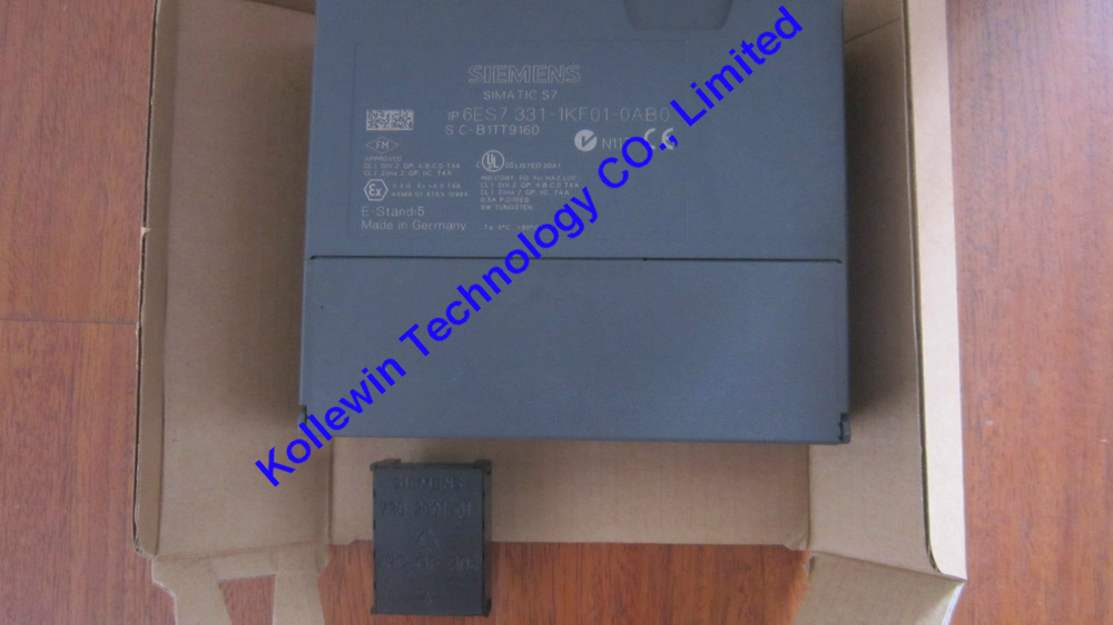
6ES7331-1KF01-0AB0
|
SM331 8 AI x 13 Bits
|
|
6ES7331-7KF02-0AB0
|
SM331 8 AI X 14 Bits
|
|
6ES7331-7PF01-0AB0
|
SM331 8 AI,RTD
|
|
6ES7331-7PF11-0AB0
|
SM331 8 AI,TC
|
|
6ES7332-5HD01-0AB0
|
SM332 4 AO x 12 Bits
|
|
6ES7332-5HF00-0AB0
|
SM 332 8 AO x 12 BITS
|
|
SIMATIC DP IM 153
|
|
6ES7153-1AA03-0XB0
|
SIMATIC DP, INTERFACE
IM 153-1, FOR ET 200M,
FOR MAX. 8 S7-300 MODULES
|
|
6ES7365-0BA01-0AA0
|
IM 365 Rack expansion module,be deployed with a central controller and a expansion rack
|
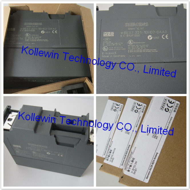
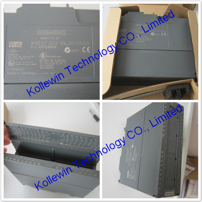
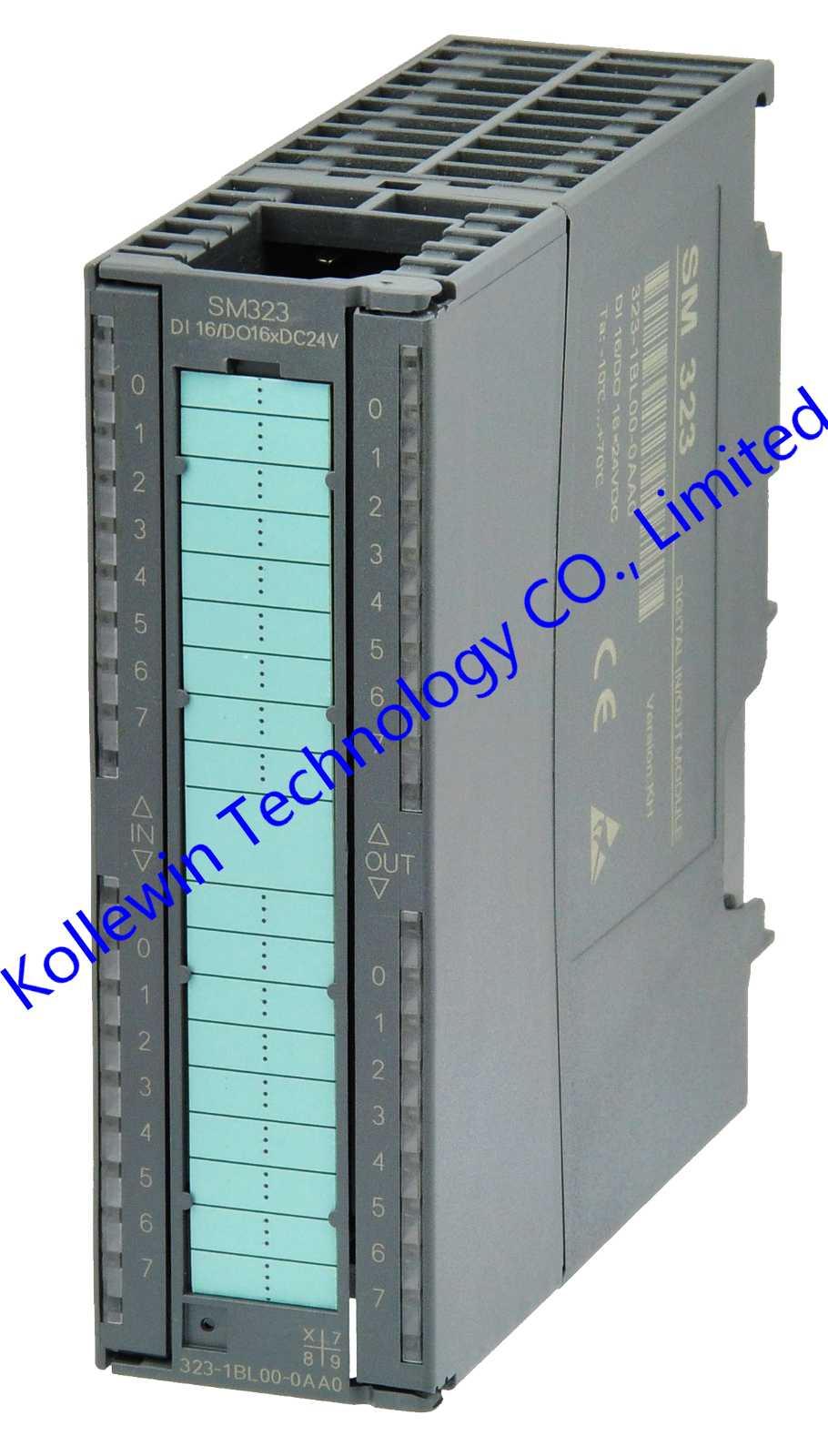
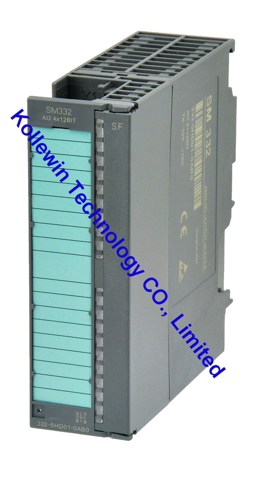
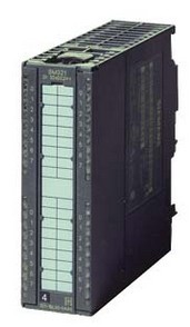
More pictures for your reference:


Please feel free to contact me for any question!
Contact person: Miss Nancy


Recent Comments