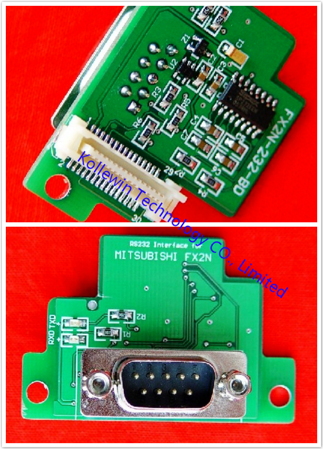
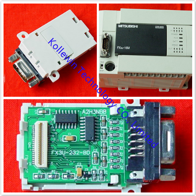
Mitsubishi FX2N-232-BD RS232 interface Board

Introduction to Mitsubishi FX2N-232-BD
The communication board FX2N-232-BD for RS232C (hereinafter referred to as “232BD”) can be connected to the main unit of the FX2N Series programmable controller, and used as the port for the following applications.
(1) To perform data transfer between RS232C devices such as personal computers, bar code readers and printers.
(2) To perform data transfer using the dedicated protocol between RS232C devices. For details of the dedicated protocol, refer to the users manual of the FX-485PC-IF.
(3) To connect a programming tool.
And when the 232BD is used for the application (1) or (2) above, the communication format including the baud rate, the parity and the data length is specified by the parameters or the contents of the special data register D8120 of the FX2N programmable controller.
Only one 232BD can be connected to one base unit. Accordingly, the 232BD cannot be used together with the FX2N-485-BD or the FX2N-422-BD. When two or more RS232C units are required to be connected for the application, use the special block for RS232C communication.
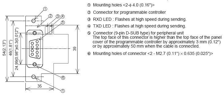
1.1 EXTERNAL DIMENSIONS of Mitsubishi FX2N-232-BD
Dimensions : mm (inches) Accessory : M3 self-tapping screws ´ 2, mounting bracket ´ 2
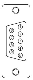
TERMINAL LAYOUTS of Mitsubishi FX2N-232-BD
The connector is a 9-pin D-SUB type, and the pin configuration is as shown below.
| Pin No. | Signal | Meaning | Function |
| 1 | CD(DCD) | CD(DCD) | ON when carrier is detected for data reception |
| 2 | RD(RXD) | Receive data | Receive data (RS232C device to 232BD) |
| 3 | SD(TXD) | Send data | Send data (232BD to RS232C device) |
| 4 | ER(DTR) | Send request |
Signal requesting preparation for data sending to RS232C device |
| 5 | SG(GND) | Signal ground | Signal ground |
| 6 | DR(DSR) | Send enable | Shows RS232C device is ready to receive |
| 7,8,9 | NC | No connection | |
SPECIFICATION of Mitsubishi FX2N-232-BD
3.1 General specification of RS232 interface PLC comunication Board
General specifications is same as those for the FX2N series programmable controller.
3.2 Power supply specification of RS232 interface PLC comunication Board
5 V DC, 60 mA is required from the programmable controller.
3.3 Specification of RS232 interface PLC comunication Board
| Transmission standard | Conforming to RS232C |
| Transmission distance | Max. 15m |
| Connector | 9-pin D-SUB type |
| Pin layout of connector |
1:CD(DCD) 2:RD(RXD) 3:SD(TXD) 4:ER(DTR) 5:SG(GND) 6:DR(DSR) 7,8,9:NC(No connection) |
| LED indicators | RXD, TXD |
| Communication method | Half-duplex communication system |
| Protocol | Programming protocol, dedicated protocol (format 1 or 4), non protocol |
| Isolation | No isolation |
3.4 Related flag and data registers of RS232 interface PLC comunication Board
| Diagnostic | devices Operation |
| M8121 | Data transmission delayed (RS instruction) |
| M8122 | Data transmission flag (RS instruction) |
| M8123 | Finished receiving data (RS instruction) |
| M8124 | Carrier detection flag (RS instruction) |
| M8126 | Global flag (dedicated protocol) |
| M8127 | On demand handshake flag (dedicated protocol) |
| M8128 | On demand error flag (dedicated protocol) |
| M8129 | On demand Byte/Word flag (dedicated protocol) |
| M8161 |
Selection of 8 bit operations for applied instructions ASC, RS, ASCI, HEX, CCD (RS instruction) |
| Diagnostic | devices Operation |
| D8120 | Communications format (RS instruction, dedicated protocol) |
| D8121 | Local station number (dedicated protocol) |
| D8122 | Amount of data to be transmitted (RS instruction) |
| D8123 | Amount of remaining data already received (RS instruction) |
| D8124 | Data header <default STX (02H)> (RS instruction) |
| D8125 | Data terminator <default ETX (03H)> (RS instruction) |
| D8127 | On demand head device register (dedicated protocol) |
| D8128 | On demand data length register (dedicated protocol) |
| D8129 | Data network ‘time-out’ timer value (dedicated protocol) |
3.5 Communication format D8120 of Mitsubishi FX2N-232-BD
To send and receive the data between the RS232C unit using the 232BD, the communication format including the
transmission speed (baud rate) and the parity must be consistent between the 232BD and the RS232C unit.
The communication format can be set using parameters or the contents of special data register D8120 of the FX2N programmable controller. Make sure to set appropriately the communication format in accordance with the RS232C unit used. For the setting method using the parameters of the FX2N programmable controller, refer to the manual of the peripheral unit used.
Make sure to turn off the power of the programmable controller and turn it on again after modifying the setting.

*1 Set to “0" when using the dedicated protocol.
*2 Effective only when no protocol (RS instruction) is selected, and has an initial value of STX (02H: Can be modified by
the user).
*3 Effective only when no protocol (RS instruction) is selected, and has an initial value of ETX (03H: Can be modified by
the user).
*4 Set to (b11, b12) = (1, 0) when using the dedicated protocol.
*5 Set to “0" when using no protocol.
3.5.1 Example program of setting of Mitsubishi FX2N-232-BD

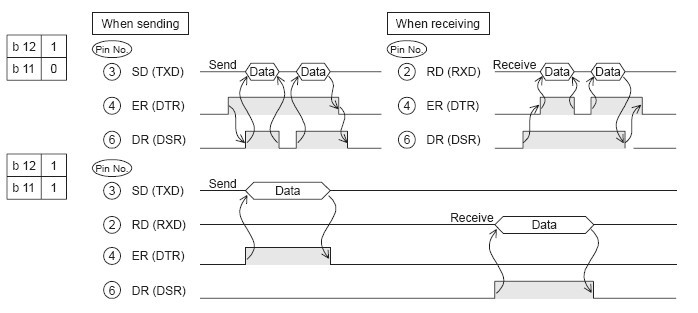
The control line is set by b12.
b12 = 0 : No hardware hand shaking. Send and receive are controlled by software protocol.
b12 = 1 : Hardware hand shaking. Signal lines ER(DTR)and DR(DSR)are used to control send and receive of data.
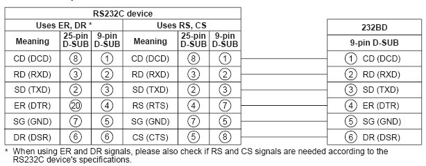
WIRING of Mitsubishi FX2N-232-BD
To connect the 232BD to RS232C device use an RS232C cable. Make sure that the shield of cables is connected to
ground (100 W or less).
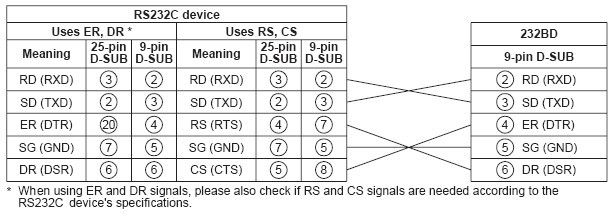
The connector of the 232BD is 9-pin D-SUB (see Section 1.2 and Chapter 2). The connections of RS232C devices
varies with each device being used. Check the specification of the device, and connect.
4.1 Connection examples
4.1.1 Terminal specification device of RS232 interface PLC comunication Board
4.1.2 Modem specification device of RS232 interface PLC comunication Board
4.1.3 When programming or monitoring of Mitsubishi FX2N-232-BD
Use F2-232CAB-1 and 25-pin D-SUB to 9-pin D-SUB adapter or make a suitable cable.
CAUTION for using Mitsubishi FX2N-232-BD
1) When programming tool is connected the 232BD, do not use any other communication format or parameters. If communication format or parameters is set, programming is not possible.
2) Only one programming tool (such as FX-10P, FX-20P, etc.) should be connected to either the programming port or the port provided on the 232BD. If a programming tool is connected to both connectors, the following may occur.
a) The program inside the programmable controller may not be consistent with the program inside the programming tool. If the program is modified or the set value for the timer or the counter is modified, a part of the program may be damaged and the programmable controller may malfunction.
b) When the sampling trace function of the programmable controller is used from both ports, the correct sampling trace result cannot be obtained.
Our company (Kollewin Technology CO., Limited) have a new product, named FX2N-232-BD.
It is 100% compatible with Mitsubishi original FX2N-232-BD.
Part#: FX2N-232-BD
The unit price is USD17.65/pc ![]()
USER'S MUNUAL PDF of Mitsubishi communication board FX2N-232-BD:
Specification of communication board FX2N-232-BD:
| Product Name | Communication Board |
| Fit for | for Mitsubishi FX1N PLC |
| Transmission Stanndard | Comforing to RS232C |
| Connector Type | Male 9 pin D-SUB |
| Voltage | DC 5V |
| Current | 60mA |
| Max.Transmission Distance | 15M |
| D-sub 9-pin Layout | 1:CD;2:RD(RXD);3:SD(TXD);4:ER(DTR);5:SG(GND);6:DR(DSR);7,8,9:NC(not used) |
| Material | Metal, Plastic |
Description of communication board FX2N-232-BD:
- Port to transfer the data using the non-procedure method between diversified RS-232C equipment such as personal computer, bar code reader and printer.
- Port to transfer the data using a dedicated protocol between an RS-232C equipment.
- Port to connect a programming tool.
- RS232C interface boards for Mitsubishi FX1N, anti-static and anti-surge.
- This is OEM product, not Mitsubishi original part.
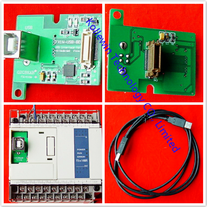
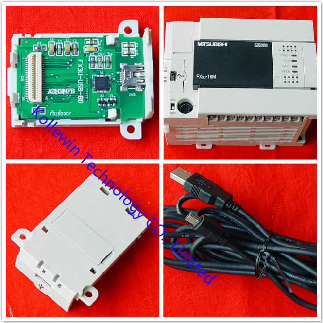
More communication boards, please click below links:
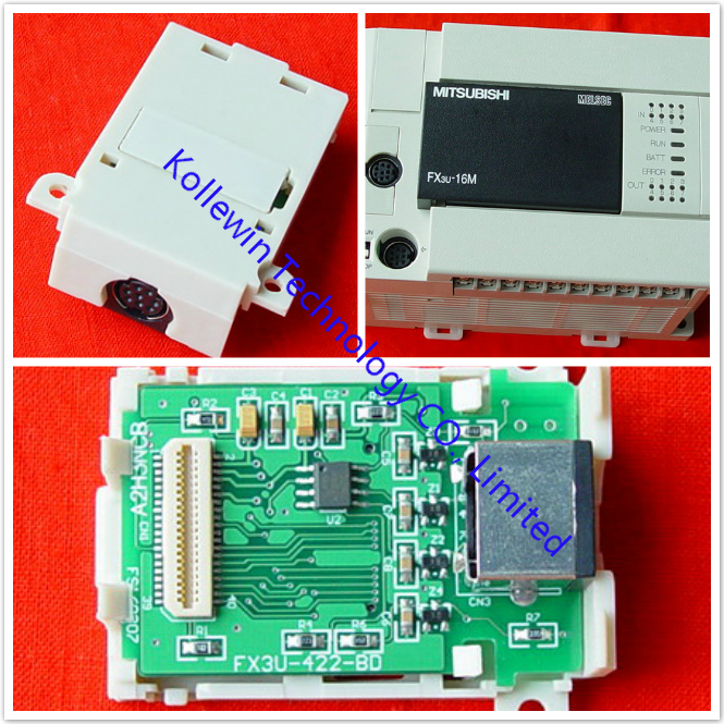
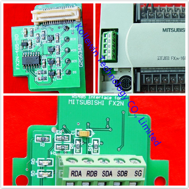
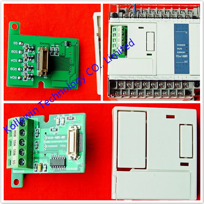
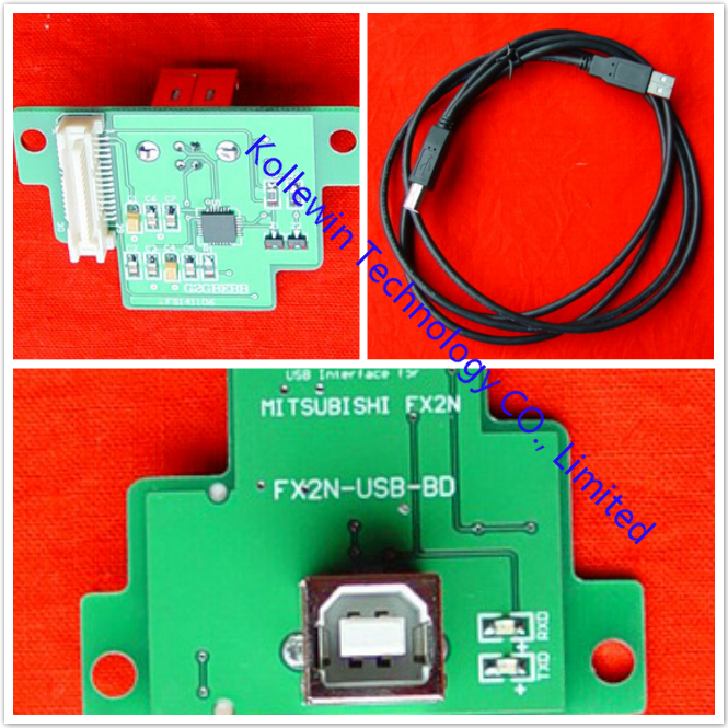
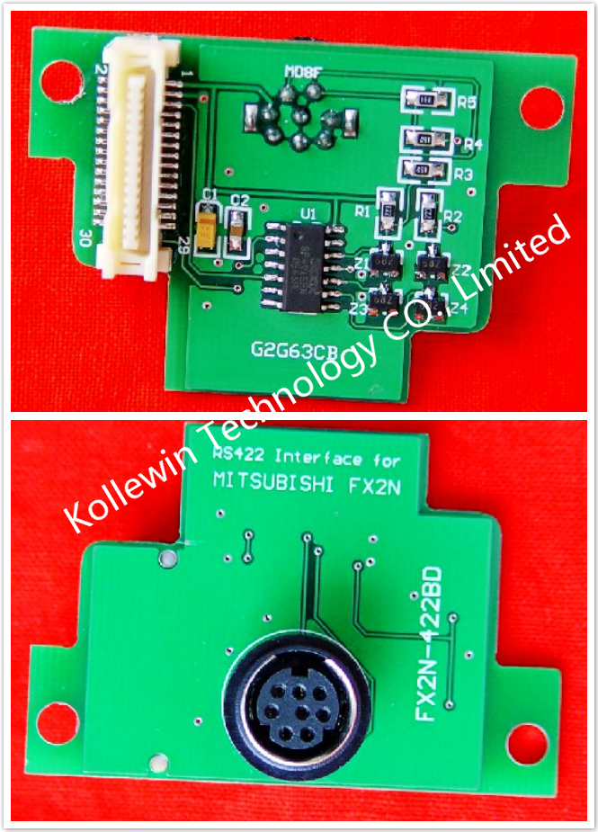
More pictures of Communication Board


Please feel free to contact me for any question!
Contact person: Miss Nancy
E-mail: nancy@kollewin.com
Tel: +86-0755-26898905-8006
Website: www.kollewin.com
Recent Comments