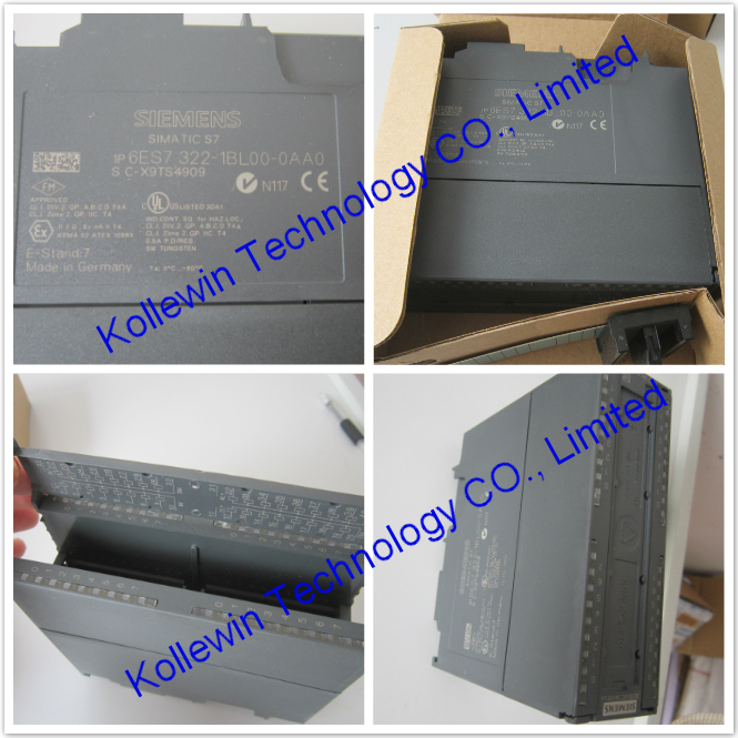
6ES7323-1BL00-0AA0 Siemens Digital output module
Properties of 6ES7323-1BL00-0AA0
Properties of SM 323; DI 16/DO 16 x DC 24 V/0.5 A:
● 16 inputs, electrically isolated in groups of 16
● 16 outputs, electrically isolated in groups of 8
● Rated input voltage 24 VDC
● Rated load voltage 24 VDC
● Inputs suitable for switches and 2-/3-/4-wire proximity switches (BEROs)
● Outputs capable of driving solenoid valves, DC contactors and indicator lights
Wiring and block diagram of SM 323; DI 16/DO 16 x DC 24 V/0.5 A

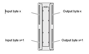
Terminal assignment of SM 323; DI 16/DO 16 x DC 24 V/0.5 A
The diagram below shows the IO addressing of channels.
Technical specifications of SM 323 6ES7323-1BL00-0AA0
|
SIMATIC S7-300, DIGITAL MODULE SM 323, OPTICALLY ISOLATED, 16 DI AND 16 DO, 24V DC, 0.5A, AGGREGATE CURRENT 4A, 1X40 PIN
|
| Supply voltage | |
| Load voltage L+ | |
| Rated value (DC) | 24 V |
| permissible range, lower limit (DC) | 20.4 V |
| permissible range, upper limit (DC) | 28.8 V |
| Input current | |
| from load voltage L+ (without load), max. | 80 mA |
| from backplane bus 5 V DC, max. | 80 mA |
| Power losses | |
| Power loss, typ. | 6.5 W |
| Digital inputs | |
| Number/binary inputs | 16 |
| Input characteristic curve acc. to IEC 61131, Type 1 | Yes |
| Number of simultaneously controllable inputs | |
| all mounting positions | |
| up to 40 °C, max. | 16 |
| up to 60 °C, max. | 8 |
| Input voltage | |
| Type of input voltage | DC |
| Rated value, DC | 24 V |
| for signal "0" | -30 to +5 V |
| for signal "1" | 13 to 30 V |
| Input current | |
| for signal "1", typ. | 7 mA |
| Input delay (for rated value of input voltage) | |
| for standard inputs | |
| at "0" to "1", min. | 1.2 ms |
| at "0" to "1", max. | 4.8 ms |
| at "1" to "0", min. | 1.2 ms |
| at "1" to "0", max. | 4.8 ms |
| Cable length | |
| Cable length, shielded, max. | 1000 m |
| Cable length unshielded, max. | 600 m |
| Digital outputs | |
| Number/binary outputs | 16 |
| Functionality/short-circuit strength | Yes; Electronic |
| Response threshold, typ. | 1 A |
| Limitation of inductive shutdown voltage to | L+ (-48 V) |
| Controlling a digital input | Yes |
| Digital outputs / Switching capacity of the outputs | |
| Lamp load, max. | 5 W |
| Load resistance range | |
| lower limit | 48 Ω |
| upper limit | 4 kΩ |
| Output voltage | |
| for signal "1", min. | L+ (-0.8 V) |
| Output current | |
| for signal "1" rated value | 0.5 A |
| for signal "1" permissible range for 0 to 60 °C, min. | 5 mA |
| for signal "1" permissible range for 0 to 60 °C, max. | 0.6 A |
| for signal "1" minimum load current | 5 mA |
| for signal "0" residual current, max. | 0.5 mA |
| Output delay with resistive load | |
| "0" to "1", max. | 100 µs |
| "1" to "0", max. | 500 µs |
| Parallel switching of 2 outputs | |
| for increased power | No |
| for redundant control of a load | Yes; only outputs of the same group |
| Switching frequency | |
| with resistive load, max. | 100 Hz |
| with inductive load, max. | 0.5 Hz |
| on lamp load, max. | 100 Hz |
| Aggregate current of outputs (per group) | |
| horizontal installation | |
| up to 40 °C, max. | 4 A |
| up to 60 °C, max. | 3 A |
| Cable length | |
| Cable length, shielded, max. | 1000 m |
| Cable length unshielded, max. | 600 m |
| Encoder | |
| Connectable encoders | |
| 2-wire sensor | Yes |
| Permissible quiescent current (2-wire sensor), max. | 1.5 mA |
| Isochronous mode | |
| Isochronous operation (application synchronized up to terminal) | No |
| Interrupts/diagnostics/status information | |
| Alarms | |
| Alarms | No |
| Diagnostic messages | |
| Diagnostic functions | No |
| Diagnostics indication LED | |
| Status indicator digital output (green) | Yes |
| Status indicator digital input (green) | Yes |
| Galvanic isolation | |
| Galvanic isolation digital inputs | |
| between the channels | Yes |
| between the channels, in groups of | 16 |
| between the channels and the backplane bus | Yes; Optocoupler |
| Galvanic isolation digital outputs | |
| between the channels | Yes |
| between the channels, in groups of | 8 |
| between the channels and the backplane bus | Yes; Optocoupler |
| Permissible potential difference | |
| between different circuits | 75 VDC / 60 VAC |
| Isolation | |
| Isolation checked with | 500 V DC |
| Connection method | |
| required front connector | 40-pin |
| Dimensions | |
| Width | 40 mm |
| Height | 125 mm |
| Depth | 120 mm |
| Weight | |
| Weight, approx. | 260 g |
USER'S manual PDF of 323-1BL00, please refer to Page 232- Page 235:
S7-300 Modules data & USER'S MANUAL
Our company (Kollewin Technology CO., Limited) have a new product,
named 6ES7323-1BL00-0AA0,
it is 100% compatible with Siemens original part.
Part#: 6ES7323-1BL00-0AA0
Unit price:USD247.00/pc ![]()
Description: S7-300 Digital output module
Manufacturer: Kollewin
Approx. Weight: 0.3 Kg
Warranty: 1 year
Origin: China
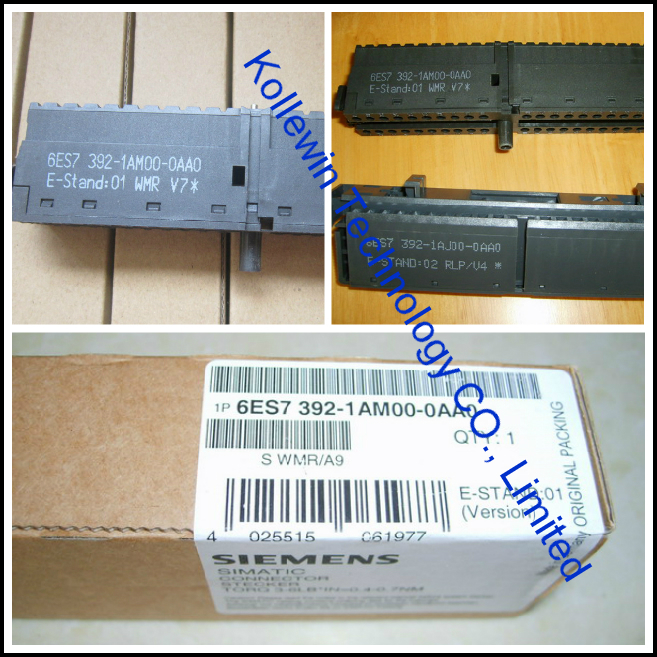
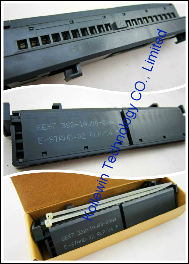
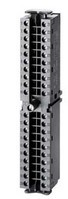
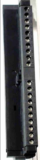
Here, you also need 1 piece of 40 pin front connector to connect with it..
Our compatible 6ES7 392-1AM00-0AA0 can meet your requirements.
6ES7 392-1AM00-0AA0 @USD16.90/pc ![]()
Technical data sheet of our SM 323 6ES7323-1BL00-0AA0
|
Model |
SM323 inputs/outputs:16 |
|
Product Description |
16DI,24VDC/16DO, 24 VDC; Transistor; Optical isolation with high immunity. |
|
Power consumption |
|
|
·From backplane bus current consumption |
80mA |
|
·Power loss |
6.5W |
|
Input Feature |
|
|
Number of digital inputs |
16 |
|
Input voltage |
|
|
·Rate value |
24V DC |
|
·For ”0” signal |
-30~5V DC |
|
·For ”1” signal |
13~30V DC |
|
Input current |
7mA |
|
Input delay |
|
|
·From “0” to “1”,Min |
1.2~4.8ms |
|
·From “1” to “0”,Min |
1.2~4.8ms |
|
Input type |
NPN |
|
Connection of 2-wire BERO sensor |
Yes |
|
Permissible quiescent current |
1.5mA |
|
Output Feature |
|
|
Number of digital outputs |
16 |
|
Short-circuit protection |
Yes,Electronic |
|
Inductive cutoff voltage |
L+(-53V) |
|
Lamp load.Max |
5W |
|
Output voltage:for ”1” signal |
Min:L+(-53V) |
|
Output current:for ”1” signal |
0.5A |
|
Isolation tested for contact |
|
|
·Between channels and backplane bus |
Yes |
|
·Per group between channels |
Yes |
|
Cable Length (Shielded) |
1,000m |
|
Cable Length (unshielded) |
600m |
|
The status indicates |
Green LED each channel |
|
Front connector |
40-pin |
|
Dimensions(W x H x D)(mm) |
40×125×120 |
|
Order Number |
323-1BL00-0AA0 |
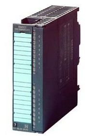
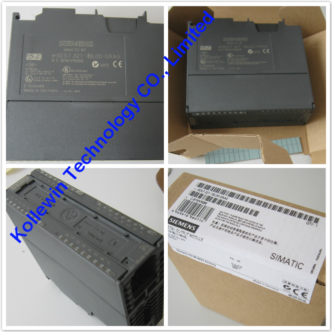
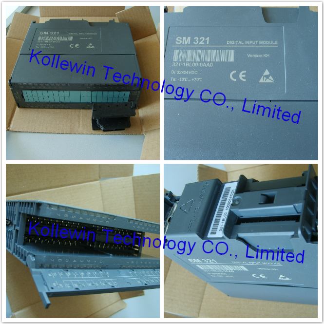
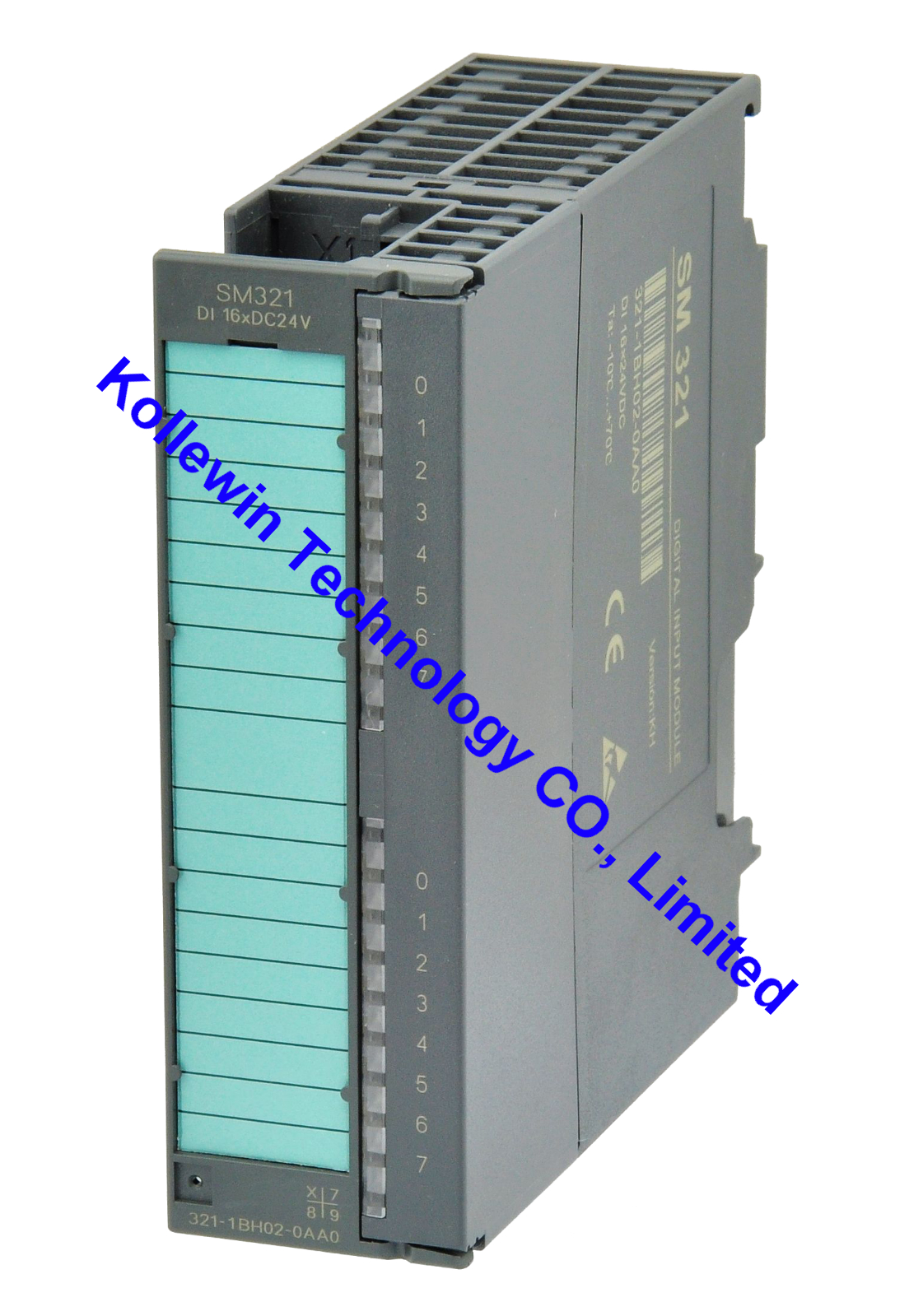
Picture of 6ES7321-1BL00-0AA0 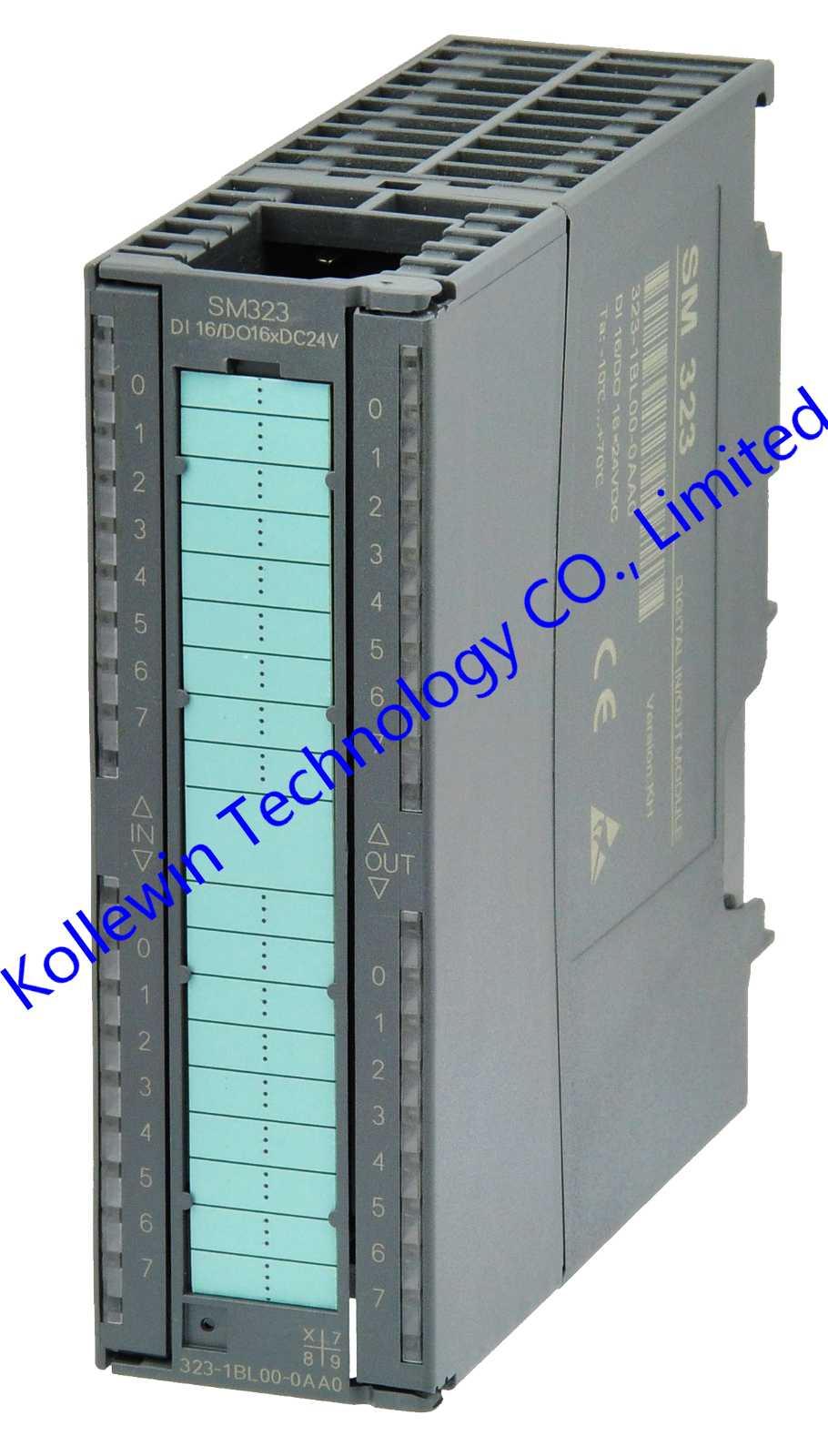
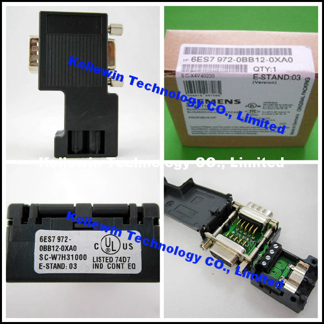
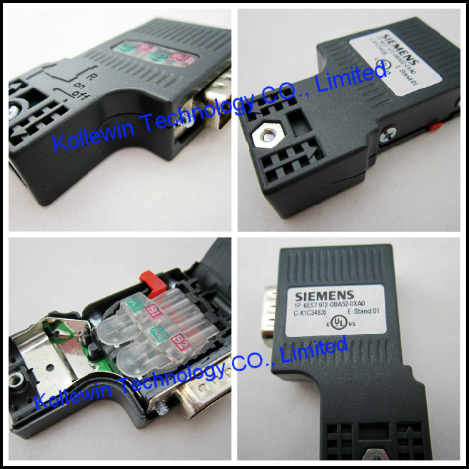
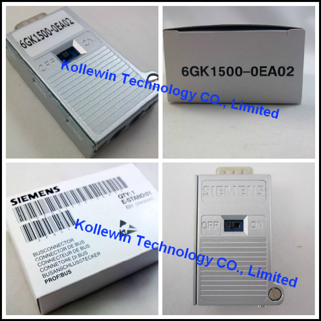
More compatible Siemens S7-200/300 modules we can offer:
| Model | Product Description |
| SM7-200 DIGITAL MODULE | |
| 6ES7221-1BH22-0XA0 | EM221 16 DI 24V DC |
| 6ES7221-1BL22-0XA0 | EM221 32 DI 24V DC |
| 6ES7222-1BF22-0XA0 | EM222 8DO,DC 24V |
| 6ES7222-1HF22-0XA0 | EM222 8DO,relay |
| 6ES7222-1BH22-0XA0 | EM222 16 DO 24V DC |
| 6ES7222-1HH22-0XA0 | EM222 16 DO RELAY |
| 6ES7222-1BL22-0XA0 | EM222 32 DO 24V DC |
| 6ES7223-1HF22-0XA0 | EM223 4DI/4DO,DC 24V relay |
| 6ES7223-1BH22-0XA0 | EM223 8 DI/ 8 DO 24V DC |
| 6ES7223-1PH22-0XA0 | EM223 8 DI 24V DC/8 DO RELAY |
| 6ES7223-1BL22-0XA0 | EM223 16 DI/ 16 DO 24V DC |
| 6ES7223-1PL22-0XA0 | EM223 16 DI 24V DC/ 16 DO RELAY |
| 6ES7223-1BF22-0XA0 | 4 DI/4DO,24 VDC |
| 6ES7221-1BF22-0XA0 | 8 DI,24V DC |
| SM7-200 ANALOG MODULE | |
| 6ES7231-0HC22-0XA0 | EM231 4 AI x 12 Bits |
| 6ES7231-0HF22-0XA0 | EM231 8 AI x 12/11 BIT |
| 6ES7231-7PC22-0XA0 | EM231 4 RTD |
| 6ES7231-7PD22-0XA0 | EM231 4 TC |
| 6ES7231-7PH22-0XA0 | EM231 8 TC |
| 6ES7231-7PL22-0XA0 | 16AI, T/C INPUT MOD, 16BIT |
| 6ES7231-7PB22-0XA0 | 2AI, RTD INPUT MOD. 16BIT |
| 6ES7232-0HB22-0XA0 | EM232 2 AO x 12 Bits |
| 6ES7232-0HD22-0XA0 | EM232 4 AO x 12 Bits |
| 6ES7235-0KD22-0XA0 | EM235 4 AI/ 1 AO x 12 Bits |
| SM7-300 DIGITAL MODULE | |
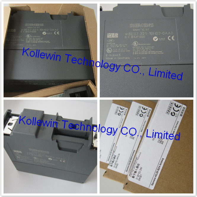
| 6ES7321-1BH02-0AA0 | SM321 16 DI 24 VDC |
| 6ES7321-1FH00-0AA0 | SM321 16 DI AC 230V |
| 6ES7321-1BL00-0AA0 | SM321 32 DI 24 VDC |
| 6ES7322-1BF01-0AA0 | SM322,8DO,24VDC,2A |
| 6ES7322-1BH01-0AA0 | SM322 16 DO 24 VDC/ 0.5A |
| 6ES7322-1HH01-0AA0 | SM322 16 DO RELAY |
| 6ES7322-1BL00-0AA0 | SM322 32 DO 24V DC/0.5A |
| 6ES7323-1BL00-0AA0 | SM323 16DI 24V DC/ 16DO 24V DC 0.5A |
| SM7-300 ANALOG MODULE | |
| 6ES7331-1KF01-0AB0 | SM331 8 AI x 13 Bits |
| 6ES7331-7KF02-0AB0 | SM331 8 AI X 14 Bits |
| 6ES7331-7PF01-0AB0 | SM331 8 AI,RTD |
| 6ES7331-7PF11-0AB0 | SM331 8 AI,TC |
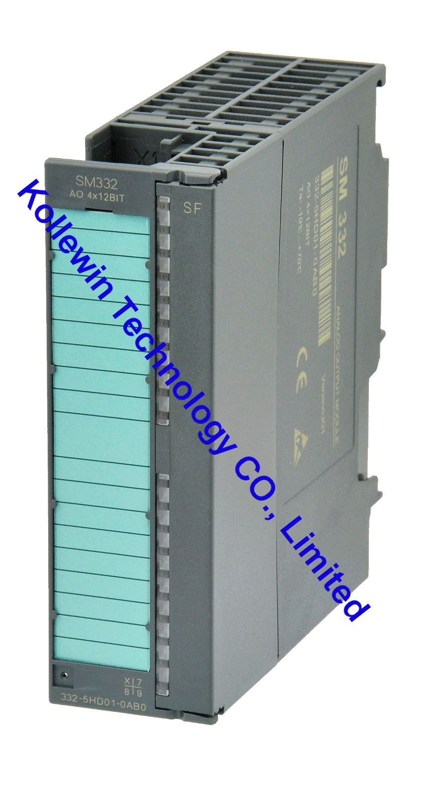
| 6ES7332-5HD01-0AB0 | SM332 4 AO x 12 Bits |
| 6ES7332-5HF00-0AB0 | SM 332 8 AO x 12 BITS |
| SIMATIC DP IM 153 | |
| 6ES7153-1AA03-0XB0 |
SIMATIC DP, INTERFACE IM 153-1, FOR ET 200M, FOR MAX. 8 S7-300 MODULES |
| 6ES7365-0BA01-0AA0 | IM 365 Rack expansion module,be deployed with a central controller and a expansion rack |
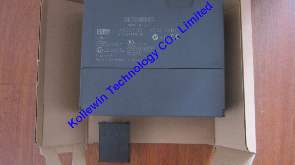
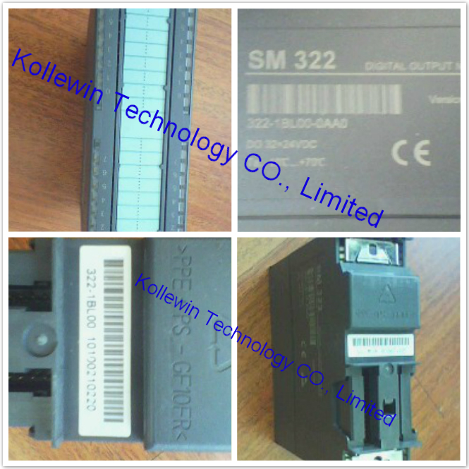
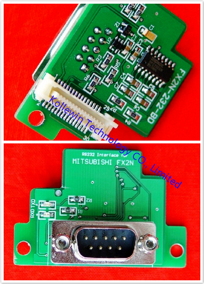
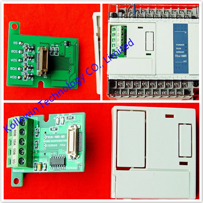
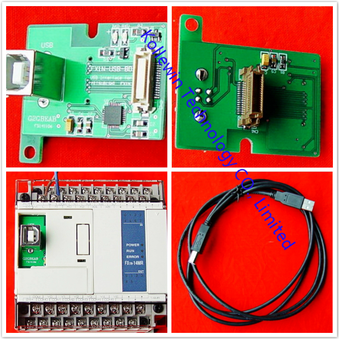
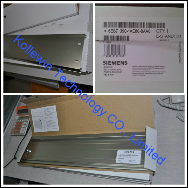
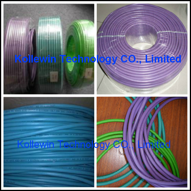
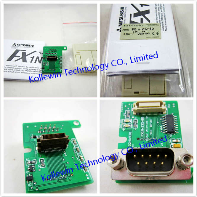
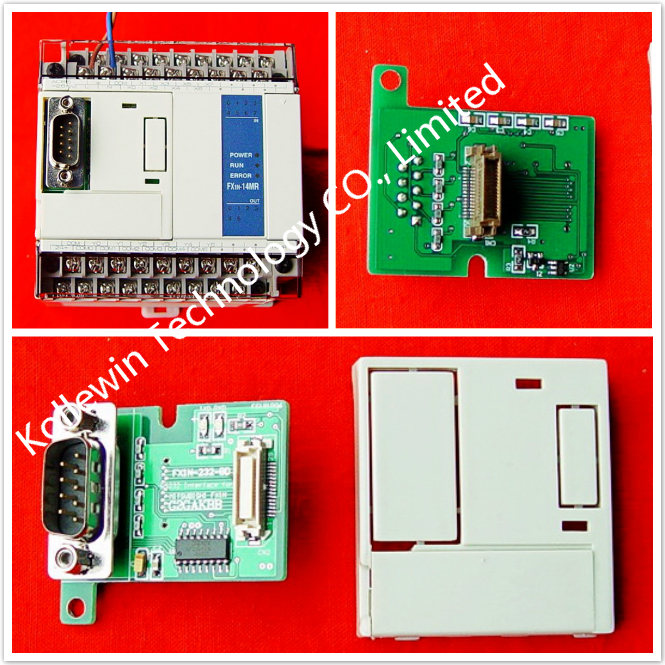
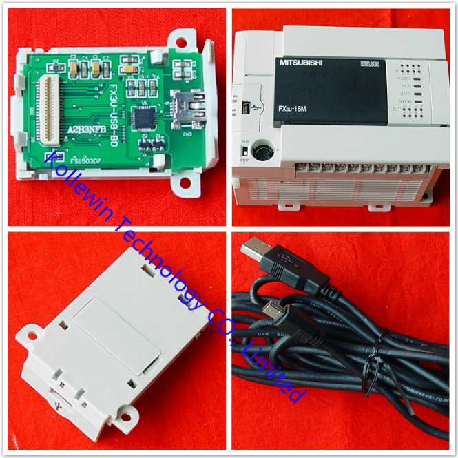
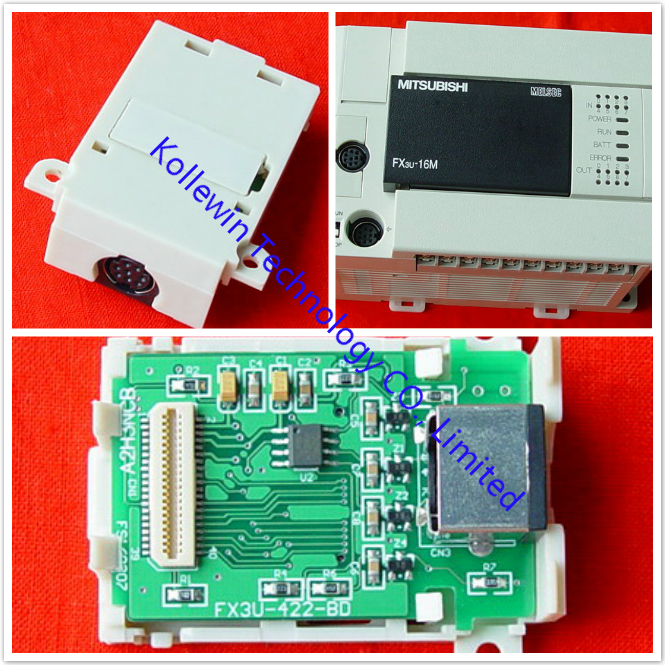
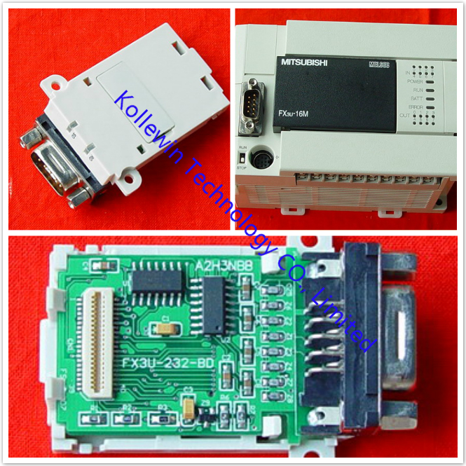
More pictures for your reference:


Please feel free to contact me for any question!
Contact person: Miss Nancy
E-mail: nancy@kollewin.com
Tel: +86-0755-26898905-8006
Website: www.kollewin.com


Recent Comments